

Hardware components | ||||||
_ztBMuBhMHo.jpg?auto=compress%2Cformat&w=48&h=48&fit=fill&bg=ffffff) |
| × | 1 | |||
| × | 3 | ||||
| × | 1 | ||||
| × | 1 | ||||
| × | 3 | ||||
| × | 1 | ||||
 |
| × | 1 | |||
Software apps and online services | ||||||
 |
| |||||
 |
| |||||
UPDATE.
OK its been a while and I should have mentioned before now but...The final version has been running for a couple of months now. It took a little tweaking to get the levels I wanted just right but that's why I marked all my variables in the sketch. More pics and the new code to follow
Not many changes in the code though.
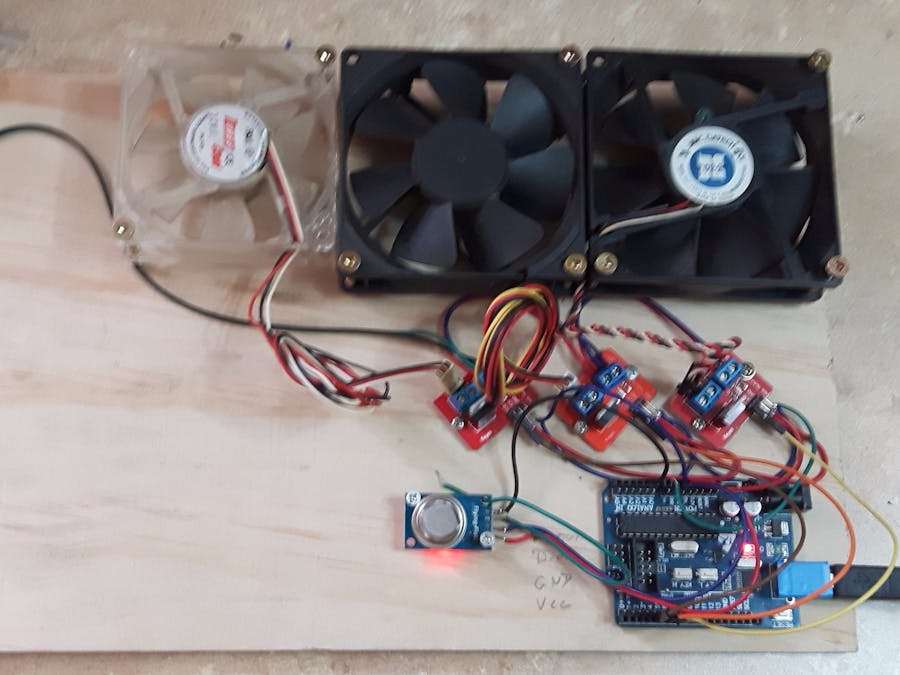
This is only a prototype so excuse the wiring. The Idea is to use 3 fans that automatically activate at different levels of room pollution.
Using more or less fans is quite simple as the sketch is pretty modular and easy to follow. Adding fancy extras such as status indicators is also an easy option by taking additional items from the 12 volt outputs of the fan or defining extra pins and including them at the same points as the individual fan activation.
MountingFor my test setup, I mounted my fans on a piece of plywood. It's optional but watch out for wandering fans if you don’t use anything. These fans are about 1 CM above the board to allow air flow.
For the final assembly I will be placing the sensor in the most vulnerable location although adding a second one is again an easy option.
The fans will be mounted on a 3 inch duct at spaced intervals and will be set at an angle to try prevent back-flow of air movement. Fan one will be nearest the main vent outlet and staged back from there so that each fan adds to the air movement.
Setup and WiringThere are examples for the MQ series sensors on the Internet that use finer calibration methods and libraries than I do, but this had to be easy enough for almost anyone to do.
I did use the digital output on the prototype and will use it in the final version to activate a better small buzzer to let me know when the system is at maximum.
There is some tuning to do with the hysteresis yet but I will deal with that area on the final one.
As a temporary connection for the fans I just used extra-long header pins and bent them to 90 degrees so I didn’t have to cut the plugs off the fans and inserted them into the modules.
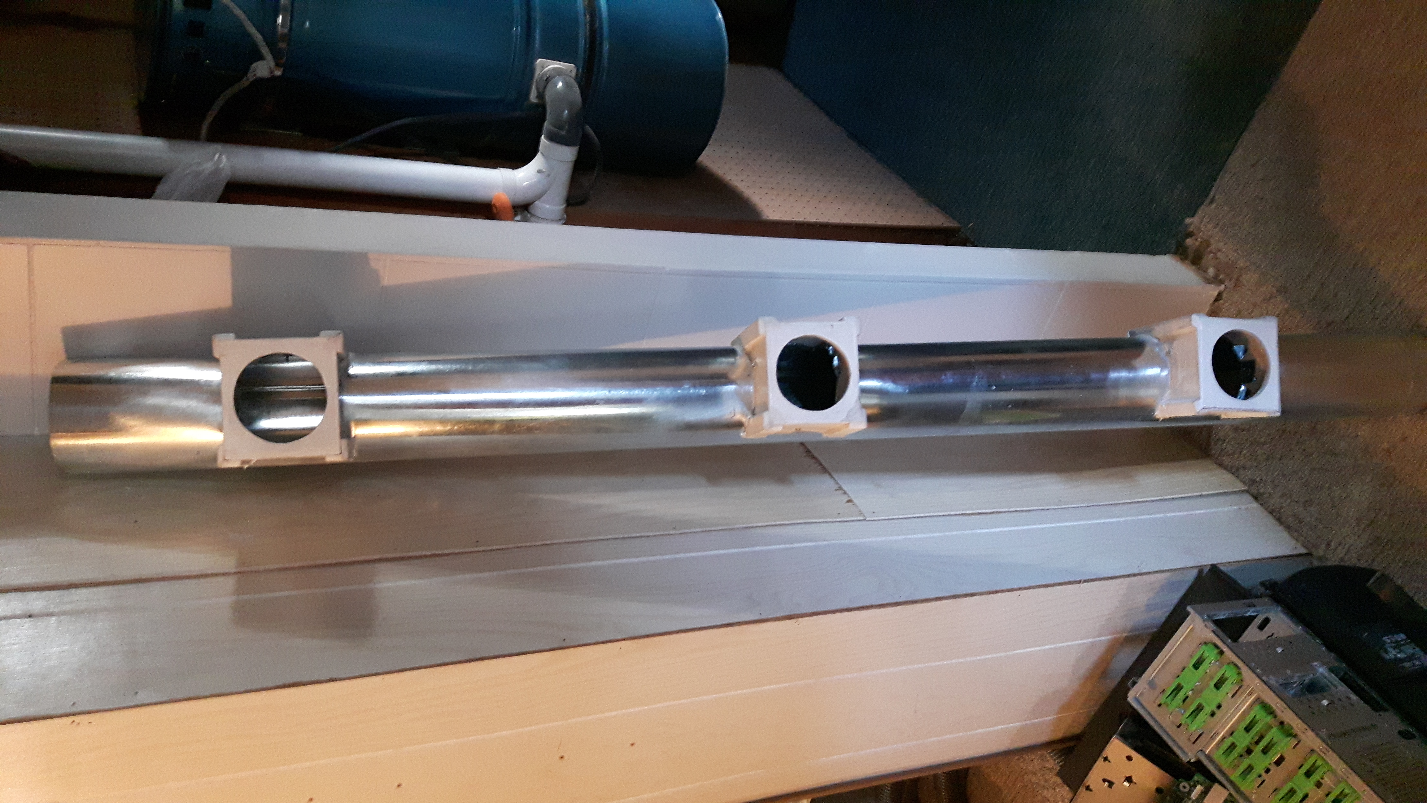
Starting assembly of the duct
Paint applied.
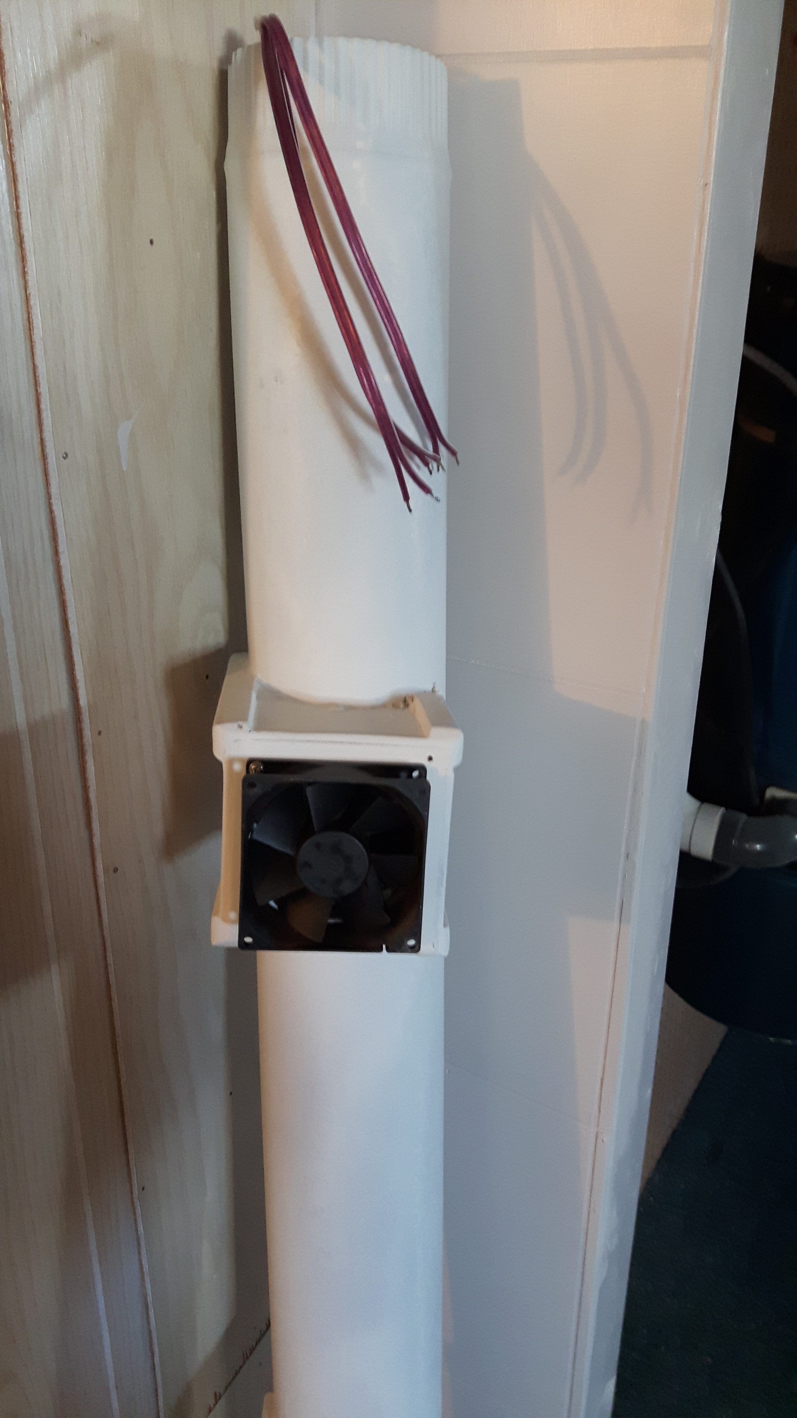
Wire loom installed in duct
Fans hooked up to loom and mounted.

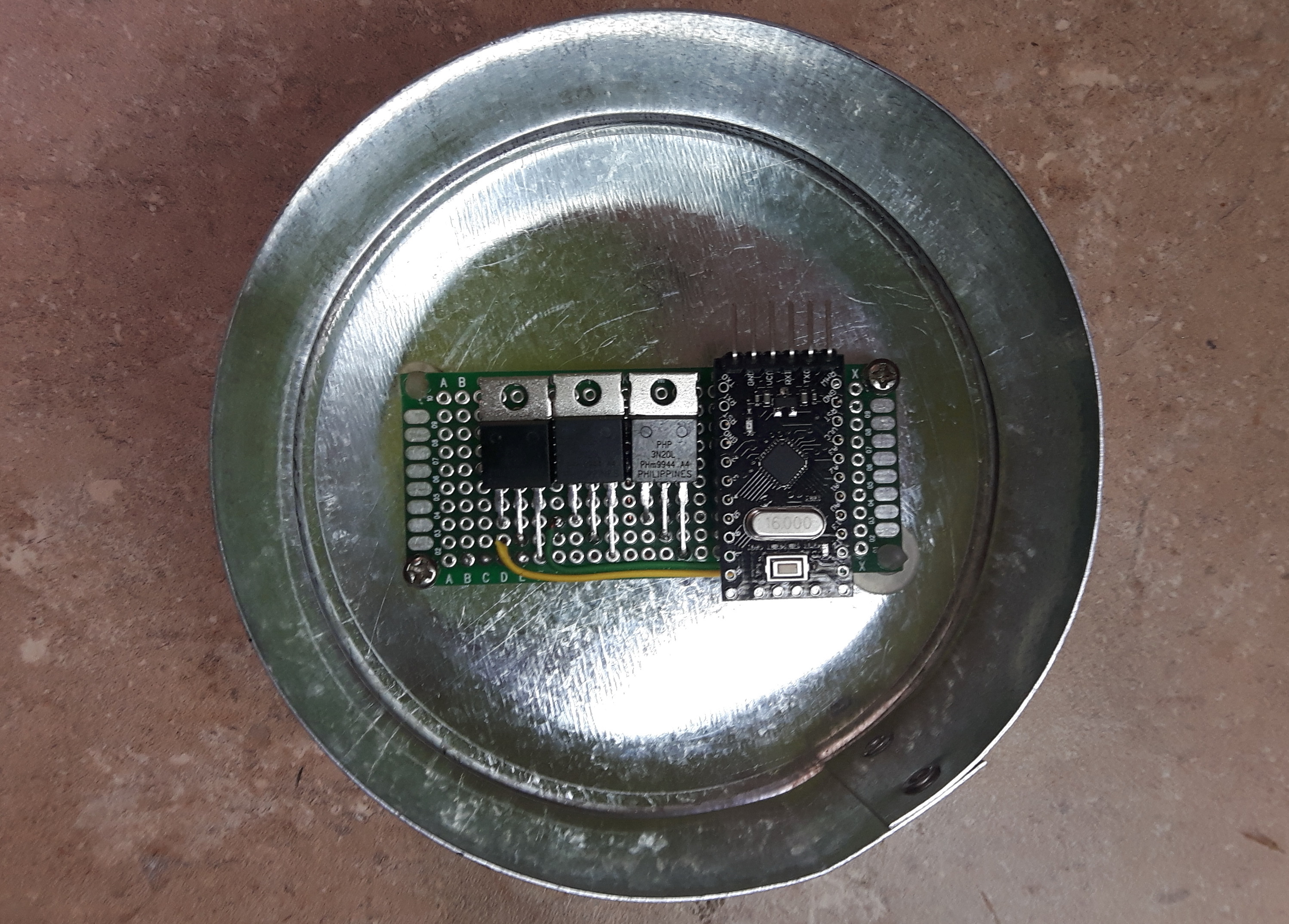
Test fit final board to end cap
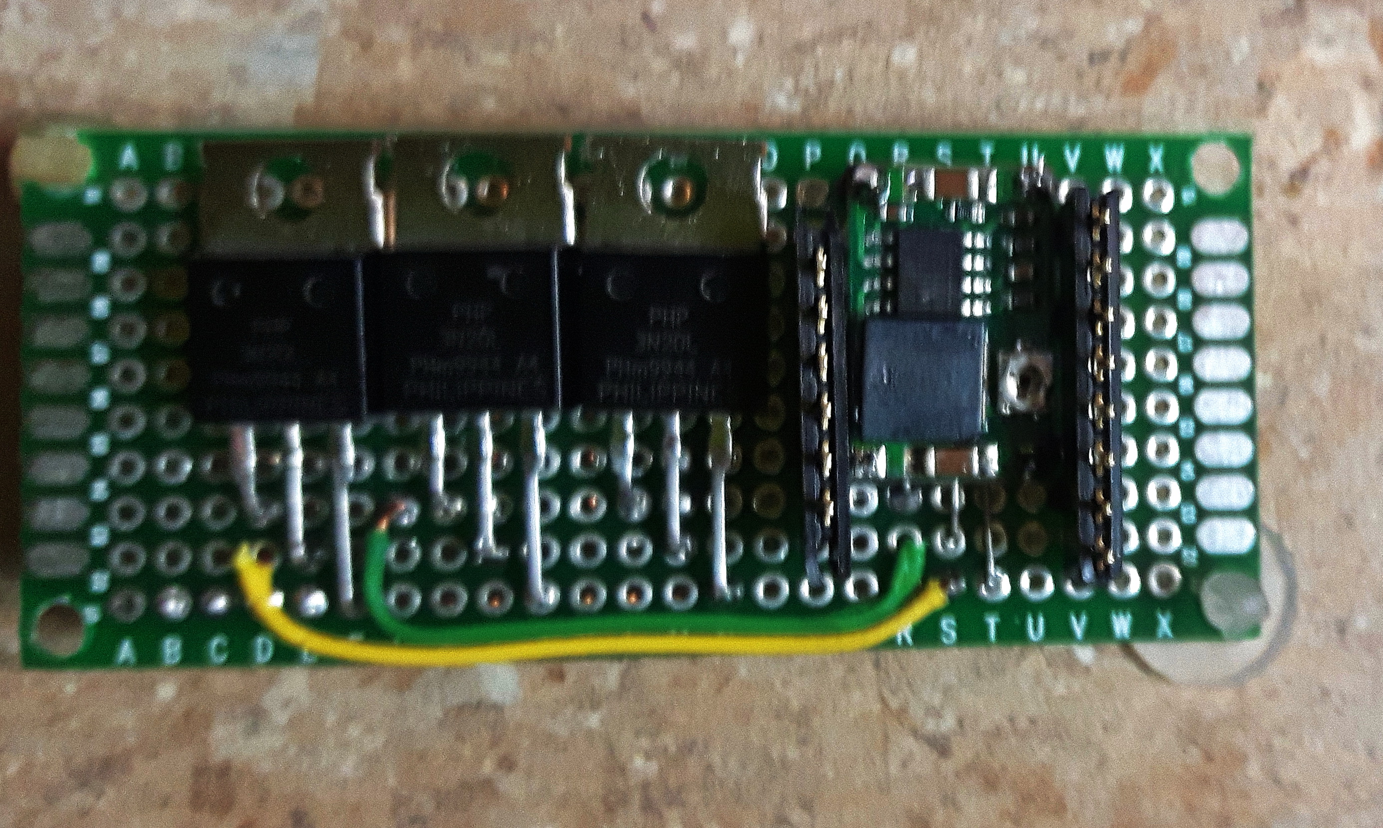
The Micro has female headers and the board below has male pins to allow disassembly. Right side of board will take the sensor and power from a voltage dropper and the left side will accept the outputs from the MOSFETS and the higher power needed for the fans.


Comments