

Hardware components | ||||||
 |
| × | 5 | |||
 |
| × | 1 | |||
| × | 5 | ||||
As always, blinky LEDs are the best way to learn hardware! This project takes you into a step-by-step journey to assemble and program a demo Hexabitz array of five RGB LED modules (H01R00) and a single 3.3V DC-DC module (H03R00).
Learn how to assemble an array, load firmware to modules, use the CLI and write your own C code. Topics covered include synchronous and asynchronous messaging, input buttons, and remote memory access.
What is it?An array of blinky LEDs to get you accustomed to Hexabitz hardware and software workflow. Feel free to send us any suggestions to improve or alternative methods you tried and worked out well
Estimated hardware build time: 10-15 minutes
Estimated software development time: 10-15 minutes for each example
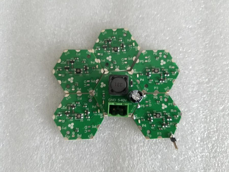
Build instructionsStep 1 - Plan your arrayPlanning is always wise before soldering things together! Stage the project components (P1) and plan your array design by aligning modules side-by-side in the shown orientation (P2) or any orientation you prefer.
It's time to do the fun stuff and assemble the array! Start by making basic solder joints to hold modules together (P3). This helps a lot moving forward.
Then complete the remaining joints. You don't have to do all of them but it's preferable to provide structural support. Don't forget to work on the bottom side (P4).
Finally add the push buttons (P5) (make sure you leave factory bootloader programming port P2 free if you did not load firmware before). Add any extra connectors/headers you might need and now hardware assembly is finished! (P6).
Check this assembly video as well:
Step 3 - Get the source codeCopy an empty H01Rx project from H01R00 code repository, rename the folder and open the uVision project located in the MDK-ARM folder (P7). You can also use firmware from the attached zip folder as well.
First, we need to add a topology definition file to tell the modules how they are going to be connected to each other. Open "project.h", uncomment topology header file definition and open topology_1.h header file. Modify this file to suite the array as shown in pictures (P8, P9 and P10). More about making topology header files later! Recompile the project once you're done.
Now time to generate individualized source code for each module bcased on its location in the array. Click on Manage Project Items and add four other targets if they're not already there. (P11). Choose each module from the dropdown menu and click on "Options for Target". Modify _module=1 in "C/C++" tab into module number (1 to 5) and modify name of executable in "Output" tab to match module number as well. Click on Batch Build >> Select All >> Rebuild.
Note 1: There's a way to automatically generate array topology files in run-time. We will feature it in other projects
Note 2: This project has a single type of programmable modules (H01R00). If you have other types of programmable modules, follow same steps by downloading their source code and adding same topology file.
Step 5 - Powering on!Moment of truth! Connect input voltage (5-40V DC) to H03R00 input connector, you should see the green power-OK LED once you power the array. You can use any 12V DC power adapter (P12 and P13).
It's time to load firmware on these modules. Connect the USB-UART cable and our handy Kelvin clamp to programming port P2 of module 1 and pay attention to polarity with respect to USB-UART cable (TXD/Top > yellow, RXD/Bottom > orange). Also don't forget to connect a jumper wire between array GND and cable GND (black).
If module is new and empty, load the appropriate hex file with ST Loader Demonstrator. If it's already programmed use the update Command in the CLI first. Please review firmware update article for detailed steps. (P14)
Load firmware to all modules based on their IDs (P15 and P16) and make sure you don't load same file! (I did that many times although I have programmed 500+ modules so far :) )
Connect to module 1 CLI and test some commands. If you want to test broadcast, disable response with:
set BOS.response none
Then type:
all.ping
Check the following screen recording of CLI tests and experiment with commands shown there:
Here's the array video for these tests:
You're all set! Next, we will start writing some actual C code to perform more complex tricks in the upcoming project logs.
Example 1 - Getting your hands dirty!Ready for some action?
This is a simple example to show you the C coding workflow. We will send a broadcast ping message to all five LED modules so that they blink their red indicator LED. The message will be repeated every 500ms.
In FrontEnd task in main.c, write the following before the infinite loop:
#if _module == 1 BOS.response = BOS_RESPONSE_NONE; #endif
And this inside the loop:
#if _module == 1 SendMessageToModule(BOS_BROADCAST, CODE_ping, 0); Delay_ms(500); #endif
Recompile Module 1 and load. Note that the ping message takes zero parameters. The destination module ID (first parameter for SendMessageToModule API) is replaced with BOS_BROADCAST constant to broadcast the message everywhere.
For more information about implementing these APIs, check our BOS documentation. Here's a step-by-step video guide for your first example!
Example 2 - Random dancing lightsMake some dancing lights using broadcasted dim Message. Since the dim message enables separate internal timers on each module they end up out-of-sync in a beautiful way :D Note how message parameters with 32-bit size are cast into byte-wide parameters.
You can copy the code below directly into a main.c file in User folder or rename the main_ex2.c file to main.c and replace the older one.
Broadcast dim (exactly as ex 2) but fully-synchronized. Module 1 emulated the dim functionality and broadcasts color Messages with varying intensity. This way you keep the timer on a single module and keep them all synced. The 500ms delay before the loop is to ensure all modules finished booting before sending first Message.
Defining a button on Module 1 and enabling its Click event. This event is used to set a flag in the event callback. The flag is used to generate some dancing lights.
Same concept as ex 4 but with a different dancing pattern on each button. The code looks long and scary but it's all the same code repeated! As shown there, you can use compiler defines:
#if _module == 1
xxxxxxxxxx
#endif
to execute specific code inside a specific module. This saves you the hassle of creating separate projects if all or some of your modules have the same part number.
Example 6 - Remote Write APIThis example demonstrates the use of remote write API.
Button 1 (connected to Module 1) is used as on/off switch for all LEDs. Button 2 is used to cycle through basic colors (WHITE, RED, BLUE, YELLOW, CYAN, MAGENTA, GREEN). Button 4 is used to increase intensity and Button 5 to decrease intensity (each click is 10%).
All modules define three BOS variables: A bool describing LED status and two UINT8 describing intensity and color. They are initialized to ON, 50(%) and WHITE respectively.
First of all, the global variables are linked to BOS variables so that we can use addresses 1, 2 and 3 to address them across the array. Then, all four buttons are defined and click event is enabled. Inside the click event, each module performs its task locally (e.g., cycling through colors) then broadcasts a RemoteWrite to the appropriate BOS variable. The indicator LED is also blinked to show the click. Inside the infinite loop, a setColor API is used to control the local LED based on the value of BOS variables shared across the array. This example shows how to use RemoteWrite to control basically everything in the array.


Comments