


Hardware components | ||||||
 |
| × | 1 | |||
| × | 1 | ||||
| × | 1 | ||||
Software apps and online services | ||||||
| ||||||
| ||||||
Hand tools and fabrication machines | ||||||
 |
| |||||
Hey everyone, and welcome back!
Meet PiBoy Advance—a DIY Game Boy built inside the shell of a Game Boy Advance, powered not by a Raspberry Pi, but by something far more minimal: the Raspberry Pi Pico.
Unlike the full-fledged Raspberry Pi that comes with operating systems and multimedia support, the Pico is a microcontroller. That means no Linux, no built-in graphics stack, and no luxury of high-level emulation frameworks. Everything—from display handling to sound generation and ROM loading—had to be engineered from scratch. And that’s exactly what makes this build special. However, we are not really building the emulator from scratch; we are using an existing Pico GB project repository. All the circuitry has been built from scratch.
PiBoy Advance runs Game Boy ROMs directly from an SD card, displays them on an ILI9225 screen, and even outputs sound using a MAX98357 I2S Module.
The shell used in this project was arranged from a local marketplace in my city, which is the Lajpat Rai market. It's one of the biggest electronics marketplaces in India; it's in front of Red Fort, New Delhi, and here you can find a bunch of old retro games and related stuff. I even got an OLED PSP and PS2 from here, which I will be using in a future project.
By following the PICO GB pinout info found on their GitHub page, I was able to make a simple circuit that houses the PICO display and the sound module together along with buttons for controls.
Additionally, because we are making a handheld device, we had to provide a stable power source, so we added a power management circuit in our setup, which uses a LiPo cell to provide power to our PICO setup.
This article covers the complete build process of the PiBoy Advance project, so let's get started with the build.
Materials RequiredThese are the materials required in this build-
- Custom PCB (Provided by NEXTPCB)
- Raspberry Pi PICO
- ILI9225 Display
- MAX98357 Audio Module- With Low Profile Speaker
- Gameboy Advance Body kit
- LiPo Cell 3.7V 1000mAh
- IP5306
- 1uH Inductor
- 10uF 50V 1206 Capacitor
- Push Button- 4.5 x 4.5 x 4.5
- SMD Push Button
- Vertical Push Button
For our Game Boy Project, we're using the Pico-GB repository created by YouMakeTech; this version was a fork of the RP2040-GB Game Boy (DMG) emulator from deltabeard. Here the PICO serves as the brain of the project. I did try to use PICO 2 and even PICO W, but this only works with the PICO RP2040.
For the display, we have to use the ILI9225 display, which runs more than 70 fps, which is insane. The original DMG project didn't support audio out, so youMakeTech modified the original file and added a few key functions that include I2S sound, meaning we had to use an I2S amplifier module. For this, we chose the MAX98357 audio module that is connected to a small form factor 1W speaker, which will provide audio output for our device. a small fun fact, this small 1W Speaker is harvested from DF ROBOT'S unihiker k10 Dev board.
Game Boy Advance ShellOne of the most important parts of this project is the Original Nintendo Game Boy Advance replacement body kit, which I purchased from a retro game vendor that sells vintage consoles like the PS1, PS2, XBOX, and others at a local electronics market.
I saw this orange Game Boy advance shell while the seller was selling replacement body kits for handheld devices, and it made me think, "Why not build the entire Game Boy from scratch?" Since the body is brand new, all I had to do was develop the circuitry, which should be really, really simple.
The D-pad, A, B, and trigger buttons are all included in this shell, along with the front and rear enclosures and a few more pieces on the left and right sides of the device.
It even features a Game Boy Advance logo and a front PC Cover, this PC cover part has an adhesive tape stick on the back, which allows us to take off the protective covering and attach it to the front body.
Shell Body EditWe can construct our PiBoy in this shell, but there is a minor glitch: the Game Boy Advance's PCB size. The existing PCB of the gameboy is smaller than our PICO and other components. To create room for the new circuit, the gameboy's battery compartment, which is located on the back end and a few pillars, must be trimmed out.
- Using nipper pliers, we began the shell body edit process by removing the screw bosses on the left and right sides of the rear end.
- The AA cell holder is then fully removed; however, we must be careful not to remove the lock mechanism, which is necessary for attaching the cell cover.
- We were able to add our own circuit inside the shell by making these two adjustments, and this step ensured that there would be no space issues.
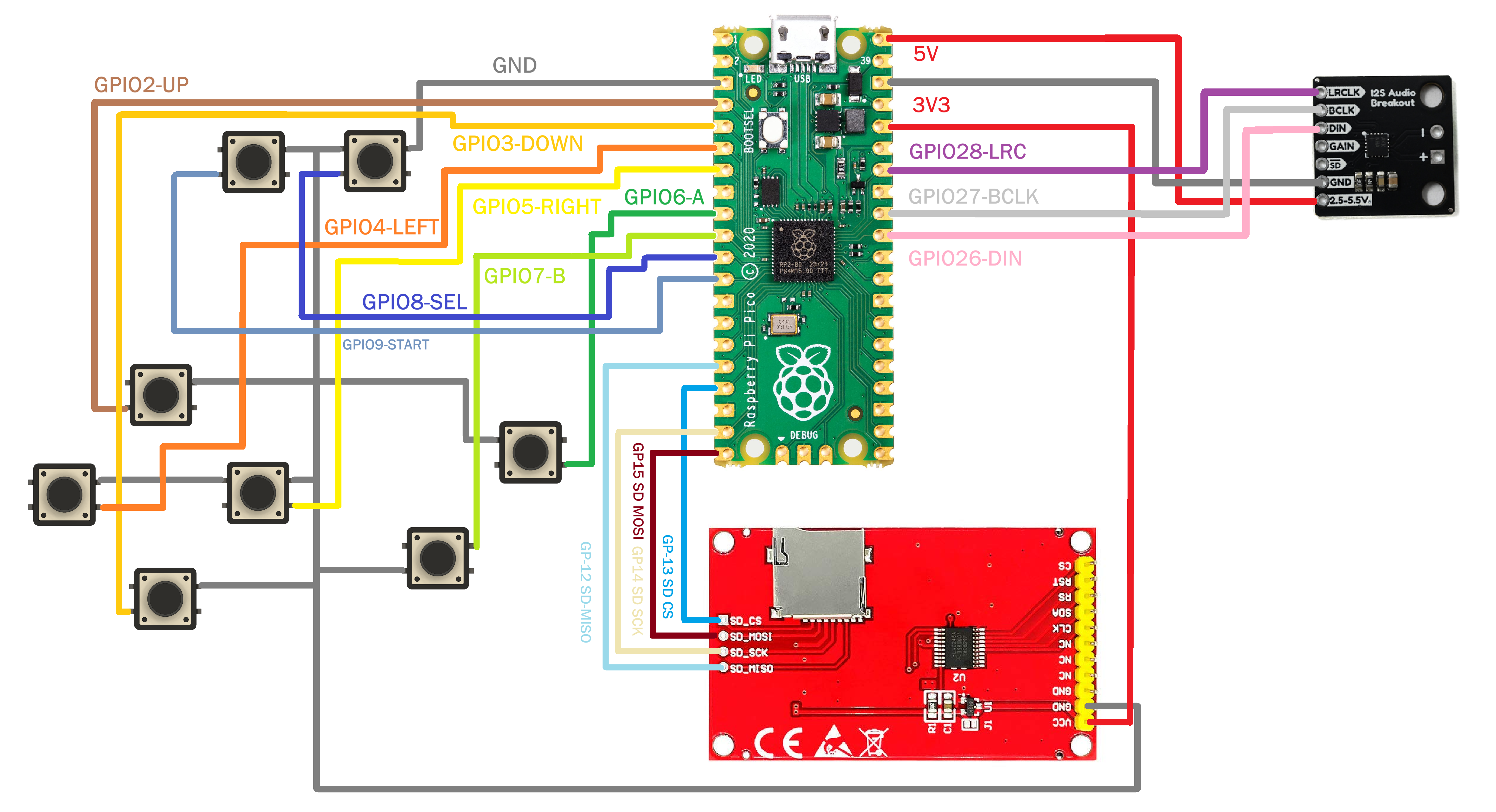
Before starting the PCB Designing process using the Pico-GB wiring scheme, I first made a complete breadboard setup. This included wiring the ILI9225 display to PICO, connecting the MAX Audio Module to PICO, and creating a button board on a perf board with eight buttons, each of which had its GPIO pin connected to PICO.
The NO Pins of each button were all connected to GND, so when a button is pressed, the GPIO attached to that button is pulled to GND, and PICO detects the button press.
The setup code was really simple: we just downloaded the uf2 file from the PICO-GB repository, pressed and held the bootsel button while connecting the USB port to PICO, and then copied and pasted the uf2 file into the PICO FLASH Storage. Re-plugging the PICO will initialize the code and cause the setup to begin working.
Game ROMs are stored on an SD card, which is connected to our PICO using the SD card breakout of the ILI9225.
After confirming that this setup is properly functioning, we move onto the next phase of this project, which is to make a custom circuit for our Game Boy Advance shell.
DESIGNNow for the toughest part of the build—designing a custom PCB to fit the shell.
Making a PCB is pretty straightforward when you control the enclosure’s shape and dimensions. If you're designing the body from scratch, you can model everything to fit perfectly. But when you're working with a random shell, especially one without any reference files, it's a whole different story.
In my case, I picked up the shell from a local electronics market. It wasn’t an official Nintendo part, just a low-cost aftermarket version that felt a bit flimsy.
I paid around ₹800 (roughly $9.50), so I wasn’t expecting perfection, but that also meant no STEP file, no clean measurements, and a lot of guesswork. Fitting a custom circuit into that kind of housing took serious trial and error.
The modeling process kicked off with a bit of luck and a lot of manual work.
I started by searching for a 3D model of the Nintendo Game Boy Advance and surprisingly, I found one that included all the key structural details: screw bosses, ribs, lips, grids, and more. It looked promising at first, but there was a catch. While the model had accurate hole placements and component outlines, the alignment was off. If I had followed it as-is, the PCB wouldn’t have matched the shell properly.
So I took the long route: manually measuring every screw boss, grid, and rib inside the shell, then correcting their positions in the 3D model. Once the geometry was dialed in, I designed a custom PCB around those mounting points. This board included push switches, the ILI9225 display, and the MAX audio module.
To validate the fit, we 3D printed the PCB and test-mounted all the components. After a few tweaks and iterations, we finally had a board that fit the shell perfectly custom-shaped and tailored specifically for this Game Boy Advance body.
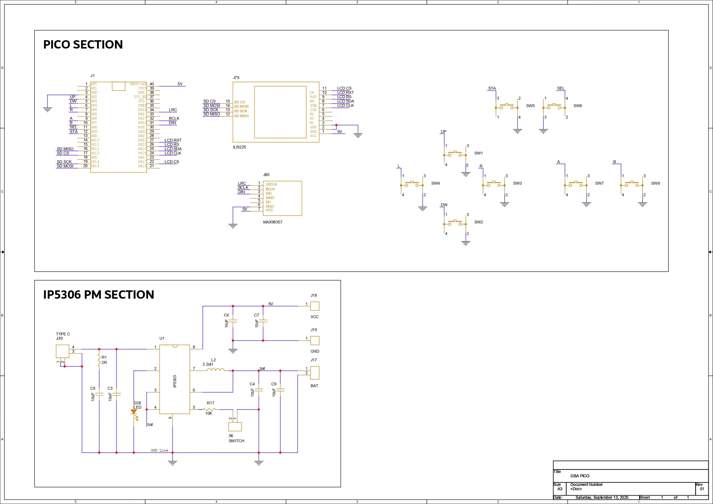
PCB DesignThe PCB for PiBoy Advance is split into two major sections: the Pico Setup and the Peripheral Connections. At the heart of it all is the Raspberry Pi Pico, which interfaces with the ILI9225 display, MAX98357 audio module, and a set of push buttons for user input.
We’ve made full use of the RP2040’s GPIOs to handle all button inputs:
- GPIO2 - Button Up
- GPIO3 - Button Down
- GPIO4 - Button Left
- GPIO5 - Button Right
- GPIO6 - Button A
- GPIO7 - Button B
- GPIO8 - Select
- GPIO9 - Start
The SD card slot of ILI9225 is wired for SPI communication with PICO through following GPIOs:
- GPIO12 - MISO
- GPIO13 - CS
- GPIO14 - SCK
- GPIO15 - MOSI
- GND - Pico GND
- VCC - Pico VBUS
The Display is powered via the Pico’s 3.3V and controlled through the following GPIOs:
- VCC - 3.3V
- GPIO22 - LCD LED
- GPIO21 - RESET
- GPIO20 - RS
- GPIO19 - SDI
- GPIO18 - CLK
- GPIO17 - LCD CS
The audio module is powered by VBUS and connected as follows:
- VCC - Pico VBUS
- GND - Pico GND
- GPIO28 - LRC
- GPIO27 - BCLK
- GPIO26 - DIN
The second major section of the PCB design focuses on power management—an essential part of any handheld device.
For the PiBoy Advance, we chose a single-cell LiPo battery as the power source, charged via a USB Type-C port. To handle power regulation, we integrated the IP5306, a compact power management IC capable of delivering a stable 5V at up to 2A from a 3.7V Li-ion or LiPo cell.
The IP5306’s output is routed directly to the VBUS pin of the Raspberry Pi Pico, which in turn powers the display, the Pico itself, and all other components on the board. It’s a clean, centralized setup that keeps the system efficient and compact.
This IC also includes smart features like low-cut and high-cut protection and a battery fuel indicator LED. During charging, the LED blinks slowly and becomes solid once the battery is fully charged. When the battery is low, it blinks rapidly every two seconds—making it easy to monitor power status without extra circuitry.
Once the schematic was finalized, we moved on to the PCB layout. The board outline shape was based on the shell dimensions, and component placement was guided by the 3D model.
The top side of the PCB houses all SMD components, including the display and push buttons, while the bottom side holds the Raspberry Pi Pico, battery terminals, and the MAX98357 audio module.
NextPCB PCB ServiceAfter completing the PCB design, Gerber data was sent to HQ NextPCB, and an order was placed for a Green solder mask with white silkscreen.
After placing the order, the PCBs were received within a week, and the PCB quality was pretty great.
In addition, I have to bring in HQDFM to you, which helped me a lot through many projects. Huaqiu’s in-house engineers developed the free Design for Manufacturing software, HQDFM, revolutionizing how PCB designers visualize and verify their designs.
Take advantage of NextPCB's Accelerator campaign and get 2 free assembled RP2040-based PCBs for your innovative projects.
https://www.nextpcb.com/blog/rp2040-free-pcba-prototypes-nextpcb-accelerator
This offer covers all costs, including logistics, making it easier and more affordable to bring your ideas to life. SMT services can be expensive, but NextPCB is here to help you overcome that hurdle. Simply share your relevant project, and they'll take care of the rest. Don't miss out on this amazing opportunity to advance your tech creations!
HQDFM: Free Online Gerber Viewer and DFM Analysis ToolAlso, NextPCB has its own Gerber Viewer and DFM analysis software.
Your designs are improved by their HQDFM software (DFM) services. Since I find it annoying to have to wait around for DFM reports from manufacturers, HQDFM is the most efficient method for performing a pre-event self-check.
This is what I see in the online Gerber Viewer. It's decent for a quick look, but not entirely clear. For full functionality—like detailed DFM analysis for PCBA—you’ll need to download the desktop software. The web version only offers a basic DFM report.
With comprehensive Design for Manufacture (DFM) analysis features, HQDFM is a free, sophisticated online PCB Gerber file viewer.
With over 15 years of industry experience, it offers valuable insights into advanced manufacturing processes. If you’re looking for reliable PCB services at a budget-friendly price, HQ NextPCB is definitely worth checking out.
PCB Assembly Process- The assembly begins with applying solder paste to each SMD pad using a dispensing syringe. For this build, we used 63/37 Sn/Pb solder paste, carefully placing it on every surface-mount pad.
- Next, each SMD component is positioned using ESD-safe tweezers, aligning them precisely over their respective pads. Once everything is in place, the board is transferred to a reflow hotplate, which heats the PCB from below until the solder paste melts and secures the components permanently.
- With the SMDs done, we move on to the through-hole components. First, the vertical push button is inserted, followed by the remaining push buttons and finally the USB Type-C port. The board is then flipped, and all THT pads are soldered from the underside to lock the components in place.
- The Raspberry Pi Pico is mounted next—positioned from the bottom side of the board, and soldered from the top to ensure a solid connection. We then use a nipper to trim the excess header pin leads, keeping the profile slim and clean.
- After that, the MAX98357 audio module is placed on the bottom side and soldered from the top. Once secured, its leads are trimmed as well. A 3mm green LED is added from the top side, soldered from the bottom, and trimmed to match the low-profile design.
- Finally, the ILI9225 display is mounted from the top side and soldered from the bottom. To wrap things up, a small speaker is attached to the front of the PCB using double-sided tape.
With all components in place and soldered, the circuit assembly is complete.
Power SourceFor PiBoy Advance, we chose a 1000mAh 3.7V LiPo cell as the power source. Its compact size made it a perfect fit inside the Game Boy Advance shell. While we initially hoped to use a higher-capacity battery, space constraints made that tricky. Thankfully, it’s not a major issue—this device draws significantly less power than typical Raspberry Pi-based emulation setups. With the 1000mAh cell, we’re getting a solid 2.5 to 3 hours of gameplay, which is honestly impressive. It even outperforms my ROG Ally, which barely manages an hour!
The battery assembly process was straightforward. We soldered the positive terminal of the LiPo to the Battery CON + pad on the PCB, and the negative terminal to the Battery CON – pad. To secure the cell to the back of the board, we used double-sided tape and press-fit it into place—keeping the setup clean, stable, and low-profile.
Shell Assembly Process- The shell assembly process, which is the most crucial step in this build, starts with the installation of all the parts included in the GBA Kit to the front half of the body. These parts include the D Pad Button, A-B Buttons, Start-Select Buttons, LED Diffuser, Left Trigger-Right Trigger, and the Left and Right Accent Part.
- The Cirucit is then positioned over the screw bosses, and the Circuit is fastened to the Front Body using four M2 screws.
- After that, we position the rear half of the body and fasten the two halves together with six M2 screws completing the assembly process.
The rear body features an AA cell holder lid. When opened, it provides easy access to the SD card slot and the Raspberry Pi Pico’s USB port, making debugging and updates straightforward.
Finishing Touches- We begin by peeling off the back protective film from the double-sided tape on the Front PC Cover provided in the kit.
- Next, we remove the protective film from the ILI9225 display.
- We then align the Front PC Cover with the Front Body and press firmly along the edges to secure it with the Front body.
- Finally, we peel off the outer protective layer from the PC Cover, revealing a clean, scratch-free surface.
With that, the assembly is complete.
RESULTSHere’s the end result of this small but seriously fun project: a handheld console that looks just like a Game Boy Advance, but inside, it’s running Game Boy games on a custom-built circuit powered by the Raspberry Pi Pico.
From the outside, it feels like a nostalgic throwback, but open it up and you’ll find a fully DIY setup—a custom PCB featuring the Pico, connected to an ILI9225 display, SD card slot, and audio module, all stitched together without relying on a full-sized Raspberry Pi board.
We ran a bunch of classics, from Tetris to Pokémon to Zelda, and the Pico handled every game flawlessly, without breaking a sweat.
Thanks to the onboard battery, we got a solid 2.5 to 3 hours of backup, which was perfect for outdoor use—we even took it trekking and played a few rounds when we reached our destination.
CONCLUSIONOverall this project has been completed, and all the files related to this project are attached, which you can use freely for making your own PiBoy Advance!
There are a few things I’m already thinking about for the next version of PiBoy Advance. First up: battery life. Right now, it runs for about three hours, which honestly isn’t enough—this thing is addictive.
As a true retro gaming enthusiast, I want longer sessions without worrying about charging, so a higher-capacity battery is definitely on the list.
Next, the game code. The current Pico GB setup doesn’t support save files, which is a big limitation for story-driven games like Pokémon or Zelda. Save functionality is a must-have, and I’ll be working on adding that in future updates.
Then there’s sound. At the moment, the music plays at full volume with no way to adjust it. It works, but it’s not ideal. I’m planning to add a potentiometer wheel in the next version so players can control the volume more comfortably.
Finally, the shell itself. I originally thought reusing a Game Boy Advance body would be easier than designing one from scratch—and it was, at first. But I ended up having to trim and modify both halves quite a bit, which makes replication tricky and time-consuming. So for the next version, I’ll be designing a custom GBA-style enclosure with all the necessary edits built in. I plan to get it SLA 3D printed, which should give it a finish close to injection-molded plastic. Most likely, I’ll use a professional SLA printing service to get that clean, polished look.
For now, the build is complete, and all the related files are included in the attachments.
Special thanks to HQ NextPCB for providing components that I've used in this project; check them out for getting all sorts of PCB or PCBA-related services for less cost.
Thanks for reaching this far, and I will be back with a new project soon.

_t9PF3orMPd.png?auto=compress%2Cformat&w=40&h=40&fit=fillmax&bg=fff&dpr=2)


Comments