


Hardware components | ||||||
 |
| × | 1 | |||
 |
| × | 1 | |||
| × | 24 | ||||
Software apps and online services | ||||||
| ||||||
 |
| |||||
Hand tools and fabrication machines | ||||||
 |
| |||||
 |
| |||||
Greetings and welcome back.
This is Pi Synth, a DIY sound sequencer synth built completely from scratch. This version uses a Raspberry Pi Pico as the main microcontroller, paired with a CD74HC4067 multiplexer IC that connects to 16 buttons used as the primary input controls for the synth.
The project was developed in two phases. The first phase was a temporary breadboard setup, where the entire synth circuit was assembled using three interconnected breadboards. This allowed the core functionality of the synthesizer to be prototyped and tested quickly.
The second phase was a more permanent PCB-based version. For this stage, a previously designed PCB breadboard was used, and the entire circuit was rebuilt on it to create a cleaner and more durable setup compared to the temporary breadboard prototype.
This project mainly serves as a demonstration platform for an upcoming, more advanced synthesizer project. The future version will include dedicated buttons, potentiometers, and a display. Silent mechanical switches will also be used so the instrument operates quietly, since the push buttons used in the current PCB version produce audible clicks when pressed.
Overall, the current Pi Synth setup functions as a demo board that will primarily be used for experimenting with and refining the code for the upcoming synthesizer. This Article covers the complete build process, including both the breadboard prototype and the more permanent PCB breadboard version.
So with that said, let’s get started.
MATERIALS REQUIREDFollowing were the materials used in this project:
- Raspberry Pi PICO 2
- CD74HC4067 Multiplexer module
- Custom PCB breadboard (Provided by NextPCB)
- Custom LED Board PCB (Provided by NextPCB)
- Push buttons 12x12
- Speaker 5W 8 Ohms
- PAM8403 Audio Amplifier
- Connecting wires
- Breadboards
In our project we used the CD74HC4067 Multiplexer IC, which allows many input signals to be read using only a few microcontroller pins. This IC acts like an electronic rotary switch: it connects one of sixteen input channels to a single output pin at a time, depending on the control signals provided.
The CD74HC4067 has 16 signal channels (C0–C15) and one common pin (SIG). Four select pins (S0–S3) determine which channel is currently connected to the common pin. By sending a binary value to these four select lines, the microcontroller can quickly choose which input channel to read. For example, when the select lines represent binary 0000, channel C0 is connected; when they represent 0001, channel C1 is connected, and so on up to C15.
In our Synth project, the multiplexer is used to expand the number of buttons that the microcontroller can read. Instead of dedicating a separate GPIO pin for each key, all buttons are connected to the multiplexer channels. The microcontroller cycles through the channels rapidly by changing the select pins and reading the shared SIG pin. This scanning happens fast enough that it appears as if all buttons are being read simultaneously.
Using the CD74HC4067 greatly reduces the number of required GPIO pins, making it possible to implement a 16-button keyboard and control inputs while using only five microcontroller pins (four select pins and one signal pin). This makes the circuit simpler, more scalable, and ideal for compact projects like this DIY synthesizer.
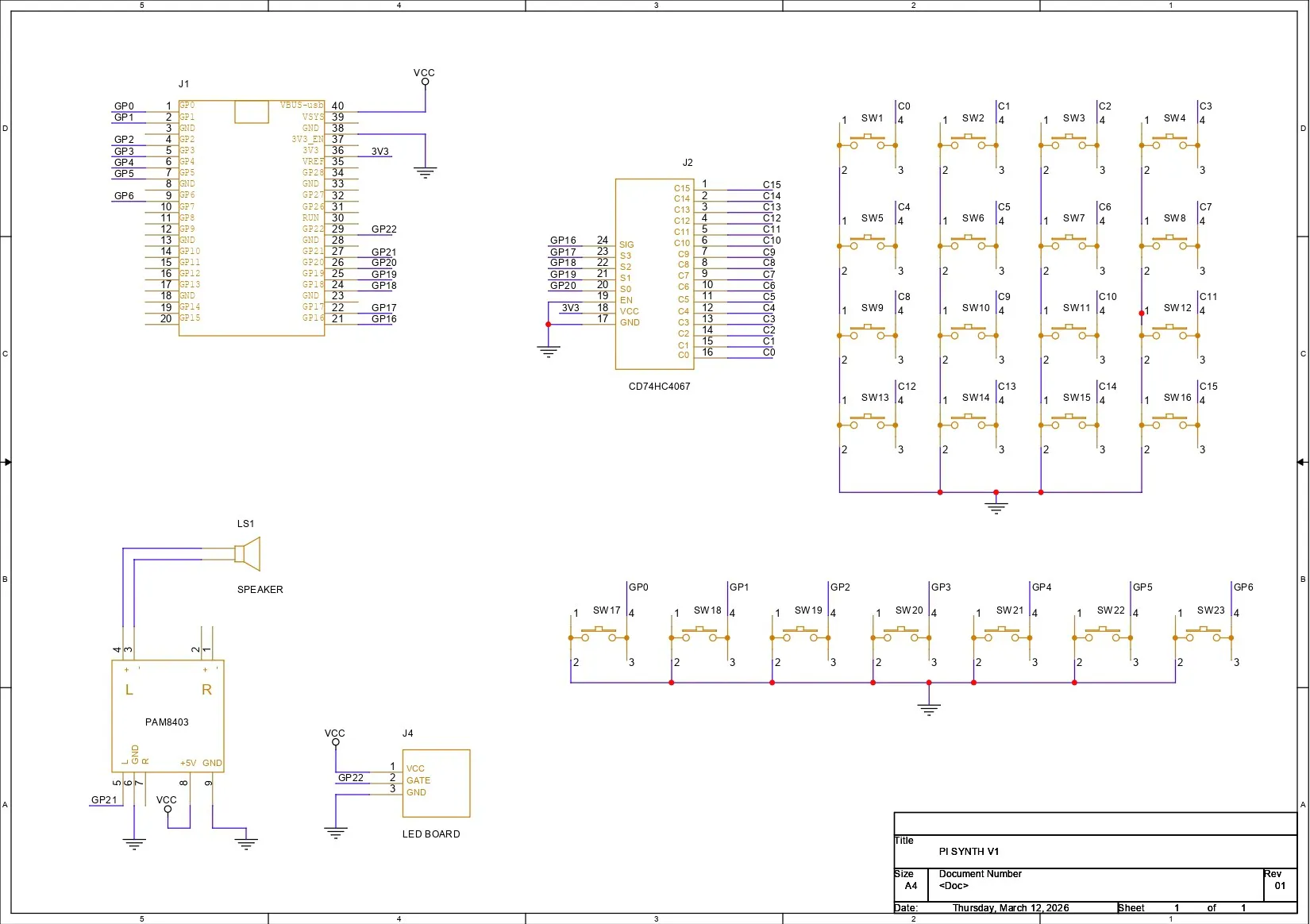
BREADBOARD SETUPUsing the provided wiring diagram, we prepared a basic breadboard setup consisting of a Pico connected to a CD74HC4067 module. We paired the S0 pin of the multiplexer with GPIO20, S1 with GPIO19, S2 with GPIO18, S3 with GPIO17, and the SIGNAL pin with GPIO16.
Sixteen buttons were connected to the sixteen channels of the multiplexer IC, and they are all connected to GND. When a button is pressed, the corresponding channel is pulled down, which is registered as a button press. The remaining buttons were paired with the remaining GPIO pins of the Pico.
For audio output, we are using a PAM8403 audio amplifier module connected to a 5W 8Ω speaker. The amplifier input is connected to GPIO21 of the Pico.
We used a total of three breadboards stacked together to create a larger breadboard surface. On this setup, we placed all the buttons, the audio module, the multiplexer, and the main microcontroller and wired everything together using single-core copper wire.
CODEThis was the main code we used in our project and it's a simple one.
#include <math.h>
// ================= MUX =================
#define S0 20
#define S1 19
#define S2 18
#define S3 17
#define SIG 16
// ================= AUDIO =================
#define AUDIO_PIN 21
#define SAMPLE_RATE 22050
// ================= LED =================
#define LED_PIN 22
// ================= RIFF BUTTON =================
#define RIFF_BUTTON 8
#define VOICES 4
// ================= NOTE TABLE =================
float noteTable[12] = {
261.63,277.18,293.66,311.13,
329.63,349.23,369.99,392.00,
415.30,440.00,466.16,523.25
};
// ================= KEY MAP =================
int keyMap[12] = {
1,3,6,0,11,8,
9,7,5,4,2,0
};
// ================= SYNTH =================
float phase[VOICES];
float subPhase[VOICES];
float freq[VOICES];
float env[VOICES];
bool voiceActive[VOICES];
float cutoff = 1200;
float lpState = 0;
int octave = 0;
// ================= DISTORTION =================
float distortionAmount = 0;
bool distortionUp = true;
bool distortionFadeOn = false;
unsigned long lastDistUpdate = 0;
#define DIST_FADE_INTERVAL 20
#define DIST_STEP 0.05
// ================= DRUM =================
bool drumOn = false;
unsigned long lastStep = 0;
int stepMs = 500;
float kickEnv = 0;
float kickPhase = 0;
// ================= RIFF =================
float riffNotes[] = {
329.63,329.63,392.00,329.63,
293.66,261.63,246.94,220.00
};
int riffLength = 8;
int riffStep = 0;
bool riffPlaying = false;
unsigned long riffTimer = 0;
int riffNoteDuration = 450;
// ================= TIMING =================
unsigned long lastAudio = 0;
unsigned long lastScan = 0;
float ledLevel = 0;
// ================= MUX =================
void selectMux(uint8_t ch)
{
digitalWrite(S0,(ch&1)?HIGH:LOW);
digitalWrite(S1,(ch&2)?HIGH:LOW);
digitalWrite(S2,(ch&4)?HIGH:LOW);
digitalWrite(S3,(ch&8)?HIGH:LOW);
delayMicroseconds(5);
}
bool readButton(uint8_t ch)
{
selectMux(ch);
return digitalRead(SIG)==LOW;
}
// ================= DISTORTION =================
void handleDistortionFade()
{
if(!distortionFadeOn) return;
unsigned long now = millis();
if(now-lastDistUpdate < DIST_FADE_INTERVAL) return;
lastDistUpdate = now;
if(distortionUp)
{
distortionAmount += DIST_STEP;
if(distortionAmount >= 1)
{
distortionAmount = 1;
distortionUp = false;
}
}
else
{
distortionAmount -= DIST_STEP;
if(distortionAmount <= 0)
{
distortionAmount = 0;
distortionUp = true;
}
}
}
// ================= SETUP =================
void setup()
{
pinMode(S0,OUTPUT);
pinMode(S1,OUTPUT);
pinMode(S2,OUTPUT);
pinMode(S3,OUTPUT);
pinMode(SIG,INPUT_PULLUP);
pinMode(AUDIO_PIN,OUTPUT);
pinMode(LED_PIN,OUTPUT);
pinMode(RIFF_BUTTON,INPUT_PULLUP);
analogWriteResolution(10);
analogWriteFreq(62500);
for(int i=0;i<VOICES;i++)
{
voiceActive[i]=false;
env[i]=0;
}
}
// ================= LOOP =================
void loop()
{
unsigned long now = micros();
handleDistortionFade();
// ---------- BUTTON SCAN ----------
if(now-lastScan > 3000)
{
lastScan = now;
bool pressed[12];
for(int i=0;i<12;i++)
pressed[i] = readButton(i);
int v = 0;
for(int i=0;i<12;i++)
{
if(pressed[i] && v<VOICES)
{
freq[v] = noteTable[keyMap[i]] * pow(2,octave);
voiceActive[v] = true;
v++;
}
}
for(int i=v;i<VOICES;i++)
voiceActive[i] = false;
// distortion toggle
static bool lastDist=false;
bool distBtn = readButton(12);
if(!lastDist && distBtn)
distortionFadeOn = !distortionFadeOn;
lastDist = distBtn;
// drum toggle
static bool lastDr=false;
bool drumBtn = readButton(13);
if(!lastDr && drumBtn)
drumOn = !drumOn;
lastDr = drumBtn;
// octave up
static bool lastOctUp=false;
bool octUp = readButton(14);
if(!lastOctUp && octUp)
octave = min(octave+1,2);
lastOctUp = octUp;
// octave down
static bool lastOctDown=false;
bool octDown = readButton(15);
if(!lastOctDown && octDown)
octave = max(octave-1,-2);
lastOctDown = octDown;
// ---------- RIFF TRIGGER ----------
if(digitalRead(RIFF_BUTTON)==LOW && !riffPlaying)
{
riffPlaying = true;
riffStep = 0;
riffTimer = millis();
}
}
// ---------- RIFF PLAYER ----------
if(riffPlaying)
{
if(millis() - riffTimer > riffNoteDuration)
{
riffTimer = millis();
freq[0] = riffNotes[riffStep];
env[0] = 0;
voiceActive[0] = true;
riffStep++;
if(riffStep >= riffLength)
{
riffPlaying = false;
voiceActive[0] = false;
}
}
}
// ---------- DRUM ----------
if(drumOn && millis()-lastStep > stepMs)
{
lastStep = millis();
kickEnv = 1.0;
kickPhase = 0;
}
// ---------- CHECK SOUND ----------
bool anyVoice=false;
for(int i=0;i<VOICES;i++)
if(voiceActive[i]) anyVoice=true;
if(!anyVoice && !drumOn && kickEnv < 0.001)
{
analogWrite(AUDIO_PIN,0);
analogWrite(LED_PIN,0);
return;
}
// ---------- AUDIO ENGINE ----------
if(now-lastAudio > 1000000/SAMPLE_RATE)
{
lastAudio = now;
float synthOut = 0;
float drumOut = 0;
int activeVoices = 0;
for(int v=0; v<VOICES; v++)
{
if(!voiceActive[v]) continue;
activeVoices++;
env[v] += (1-env[v])*0.04;
phase[v] += freq[v]/SAMPLE_RATE;
if(phase[v]>=1) phase[v]-=1;
subPhase[v] += freq[v]*0.5/SAMPLE_RATE;
if(subPhase[v]>=1) subPhase[v]-=1;
float osc =
((phase[v]*2-1)*0.6 +
((subPhase[v]<0.5)?0.6:-0.6)*0.4)
* env[v];
synthOut += osc;
}
if(activeVoices>0)
synthOut /= activeVoices;
synthOut *= 1.8;
float c = 2*sin(PI*cutoff/SAMPLE_RATE);
lpState += c*(synthOut-lpState);
synthOut = lpState;
if(distortionAmount>0.01)
{
float drive = 1 + distortionAmount*3.5;
synthOut *= drive;
if(synthOut>0.65) synthOut=0.65;
if(synthOut<-0.65) synthOut=-0.65;
}
// ---------- KICK DRUM ----------
if(kickEnv > 0.001)
{
float kickFreq = 65 + kickEnv*120;
kickPhase += kickFreq/SAMPLE_RATE;
if(kickPhase > 1) kickPhase -= 1;
drumOut += sin(2*PI*kickPhase) * kickEnv * 1.5;
kickEnv *= 0.975;
}
float out = synthOut + drumOut;
out = constrain(out,-1,1);
analogWrite(AUDIO_PIN,(out+1)*512);
// ---------- LED AUDIO METER ----------
float level = fabs(out);
ledLevel = ledLevel*0.6 + level*0.4;
int brightness = constrain(ledLevel*1400,0,1023);
analogWrite(LED_PIN,brightness);
}
}
This was the main code we prepared for the barebone working setup, here we are using CD74HC4067 which contains four channel pins S0-S3 that read which channel is active and a SIGNAL Pin that reads the button signal.
Using the below section selects which button channel is connected.
void selectMux(uint8_t ch)Each channel is selected using a 4-bit binary value, where S0 represents the least significant bit (LSB) and S3 represents the most significant bit (MSB).
For example, to select C0, the select pins are set as S3 = 0, S2 = 0, S1 = 0, and S0 = 0, which gives the binary value 0000. For C1, the pins become S3 = 0, S2 = 0, S1 = 0, and S0 = 1, resulting in 0001.
Following the same pattern, C2 corresponds to 0010, C3 corresponds to 0011, C4 corresponds to 0100, and the sequence continues in this manner until C15, which corresponds to the binary value 1111.
#define AUDIO_PIN 21
#define SAMPLE_RATE 22050
Our synth outputs audio using PWM on GPIO21.
analogWriteResolution(10);
analogWriteFreq(62500);
Using the above section, we create 10-bit audio resolution and 62.5 kHz PWM carrier; the waveform is converted into sound by the amp.
#define LED_PIN 22we added an LED RING to GPIO22; this LED shows sound intensity.
ledLevel = ledLevel*0.6 + level*0.4;
analogWrite(LED_PIN,brightness);
This section creates a smooth brightness value so the led ring reacts smoothly to sound.
#define VOICES 4We added four simultaneous notes; arrays store oscillator data for each voice.
float phase[VOICES];
float subPhase[VOICES];
float freq[VOICES];
float env[VOICES];
bool voiceActive[VOICES];
Then we have a note table.
float noteTable[12]The C note is set at 261.63 Hz, D is set at 293.66 Hz and so on.
int keyMap[12]using this, we arrange our setup in a Do-Re-Mi-styled layout.
We also added a Distortion effect in our setup, which turns ON when we toggle the distortion button.
float distortionAmountusing this, distortion increases and decreases automatically.
There is also a drumbeat generator, which works but not that great and it's currently in development.
float kickEnv
float kickPhase
The kick works by generating a low sine wave, lowering its frequency quickly, and also reducing amplitude over time.
float kickFreq = 65 + kickEnv*120;This creates a pitch drop typical of kick drums.
if(now-lastScan > 3000)Every 3 milliseconds, buttons are scanned and the code loops through all multiplexer channels.
pressed[i] = readButton(i);When pressed, a note is assigned.
We uploaded the code into our PICO Setup, please note that we are only using 16 active buttons in the code; we have other buttons, but they are unassigned and connected to the GPIO Pins of the PICO.
LEVEL 2- DESIGNFor Level 2 of our project, we first took our PCB breadboard 3D model and added 12×12 size push buttons on the PCB. Each PCB contains 12 buttons, and we added two switch boards that contain 12 push buttons each.
We used another PCB breadboard and added the 3D model of the Raspberry Pi Pico. We also added a speaker 3D model in our design and an LED PCB ring 3D model.
We also reused one of the PCBs from a previous project, the Mega Man Blaster, which uses an LED ring PCB. We will be using this PCB in our project as a sound-reactive light or sound status indicator that glows according to the audio.
By including all these 3D models, we prepared a frame part that mounts both the switch boards, the driver board, the speaker, and the LED ring in place.
After finalizing the 3D model and exporting the frame part, we 3D printed the frame using transparent PLA, and this will be our test setup for Level 2 of the project.
PCB BREADBOARDFor this project, I used one of my previously designed PCB breadboards, created specifically to suit my personal prototyping workflow.
The board includes an integrated USB Type-C input for power delivery, along with an M7 forward diode for reverse polarity protection. This ensures safe and reliable operation during development and testing.
To support SMD prototyping, a dedicated SOIC-8 footprint was incorporated into the design. This makes it possible to work with surface-mount ICs in SOIC-8 packages, which is particularly useful when a component is not available in a through-hole variant.
For added functionality and visual feedback, the PCB also features a footprint for a WS2812B addressable RGB LED. Additionally, a 0603 LED footprint is included for simple status indication when required.
The overall layout mirrors that of a traditional solderless breadboard, allowing for a familiar workflow. However, unlike a standard breadboard where the central columns are internally connected vertically, the middle section of this PCB consists of individual, unconnected pads. This design enables complete flexibility, allowing custom connections to be created manually rather than being constrained by fixed internal traces.
The VCC and GND rails are arranged identically to a conventional breadboard, ensuring an intuitive transition from temporary breadboard prototyping to a more permanent PCB-based implementation.
Check out more about this project from the previous article.
https://www.hackster.io/Arnov_Sharma_makes/dc-pump-driver-with-custom-pcb-breadboard-cdf568
LED BOARD (FRONT BLASTER PCB FROM MEGAMAN PROJECT)One of the other boards we have used in this project was the LED BOARD which was actually prepared for our previously created magaman project.
In this board we have used 10 red LEDs in 2835 packages, all connected in parallel, with each LED drawing around 0.1 W of power. One or two LEDs can be directly connected to a GPIO pin, but using this many LEDs is not recommended, as it can damage the board.
To prevent this, we used an N-channel MOSFET as a switching setup to drive the LEDs. The VCC terminal is connected to the anodes of all the LEDs, while the cathodes of the LEDs are connected to the drain of the MOSFET IC, which in our case is the 8205S. The source of the MOSFET is connected to GND.
We have added two 10 kΩ resistors: one is connected between the DIN pin and the gate of the MOSFET, and the other is connected between the gate and source. Additionally, we have added four 1206-package current-limiting resistors between VCC and the anodes of the LEDs. These resistors limit the current passing through the LEDs and protect them from overcurrent.
For this board, the LEDs are placed in a circular pattern, which is time-consuming to design directly in PCB CAD software. To simplify this, I exported the DWG file of the entire board from the CAD model and imported it into my PCB CAD software. Using the LED outlines from the DWG file as a reference, I aligned and placed the SMD LEDs accurately. This allowed us to create the front blaster PCB exactly as per the CAD model.
NextPCB PCB SERVICEAfter completing the PCB design, Gerber data was sent to HQ NextPCB, and an order was placed for a yellow solder mask with white silkscreen.
After placing the order, the PCBs were received within a week, and the PCB quality was pretty great.
In addition, I have to bring in HQDFM to you, which helped me a lot through many projects. Huaqiu’s in-house engineers developed the free Design for Manufacturing software, HQDFM, revolutionizing how PCB designers visualize and verify their designs.
Take advantage of NextPCB's Accelerator campaign and get 2 free assembled RP2040-based PCBs for your innovative projects.
https://www.nextpcb.com/blog/rp2040-free-pcba-prototypes-nextpcb-accelerator
This offer covers all costs, including logistics, making it easier and more affordable to bring your ideas to life. SMT services can be expensive, but NextPCB is here to help you overcome that hurdle. Simply share your relevant project, and they'll take care of the rest. Don't miss out on this amazing opportunity to advance your tech creations!
HQDFM: Free Online Gerber Viewer and DFM Analysis ToolAlso, NextPCB has its own Gerber Viewer and DFM analysis software.
Your designs are improved by their HQDFM software (DFM) services. Since I find it annoying to have to wait around for DFM reports from manufacturers, HQDFM is the most efficient method for performing a pre-event self-check.
This is what I see in the online Gerber Viewer. It's decent for a quick look but not entirely clear. For full functionality—like detailed DFM analysis for PCBA—you’ll need to download the desktop software. The web version only offers a basic DFM report.
With comprehensive Design for Manufacture (DFM) analysis features, HQDFM is a free, sophisticated online PCB Gerber file viewer.
With over 15 years of industry experience, it offers valuable insights into advanced manufacturing processes. If you’re looking for reliable PCB services at a budget-friendly price, HQ NextPCB is definitely worth checking out.
SWITCH BOARD ASSEMBLYFor our project, we prepared two identical switchboards using two PCB breadboards.
- On each PCB, we installed 12×12 mm push buttons, placing 12 buttons on each board, with six on the top row and six on the bottom row.
- After placing the push buttons, we flipped the board over and soldered the leads of the push buttons.
We prepared Mainboard that consisted of a Raspberry Pi PICO added to our PCB breadboard that already had a type C port soldered on board. We added a type C Port VCC with VBUS of PICO, GND to GND.
We added the CD74HC4067 module and connected its VCC with PICO's 3V3 pin and GND with GND of PICO.
S0 of Multiplexer is connected with GPIO20 of the PICO, S1 is connected with GPIO19, S2 is connected with GPIO18, S3 is connected to GPIO17 and the SIGNAL pin is connected to GPIO16.
AUDIO AMPLIFIER SETUPFor audio, we are using a PAM8403 audio amplifier board, where the right channel is used for inputting audio from GPIO21 of the Raspberry Pi Pico. An 8-ohm 5W speaker is paired with the amplifier for sound output.
- To make the connections, we placed the audio module on our PCB breadboard beside the Raspberry Pi Pico.
- The 5V pin of the audio module is connected to the VBUS pin of the Pico, and GND is connected to GND.
- The R-IN pin of the amplifier is connected to GPIO21 of the Pico.
We also added a longer wire from the output of the audio amplifier to the speaker to complete the audio connection.
LED BOARD ASSEMBLY- The process starts by applying solder paste to each component pad on the PCB.
- Once the solder paste is applied, Five SMD Blue 3030 LEDs are placed onto their respective locations. This is followed by placing the MOSFET IC and the SMD resistors, using tweezers to accurately position each component.
- After all components are placed, the PCB is carefully transferred to a reflow hot plate. The hot plate heats the PCB from below until it reaches the solder paste melting temperature. As the board reaches 200°C, the solder paste reflows and securely bonds all components to the PCB.
To make sure the LED board was working properly, we prepared a small demo sketch that blinks the LED in Morse code spelling “HI.”
This test was completely unnecessary for the project, but it was a fun little experiment.
We uploaded the code to another Pico placed on a breadboard. The gate pin was connected to GPIO0, VCC was connected to the VBUS pin of the Pico, and GND was connected to GND.
const int ledPin = 0;
const int dotTime = 200;     // duration of a dot
const int dashTime = dotTime * 3;
const int symbolGap = dotTime;
const int letterGap = dotTime * 3;
void dot() {
digitalWrite(ledPin, HIGH);
delay(dotTime);
digitalWrite(ledPin, LOW);
delay(symbolGap);
}
void dash() {
digitalWrite(ledPin, HIGH);
delay(dashTime);
digitalWrite(ledPin, LOW);
delay(symbolGap);
}
void setup() {
pinMode(ledPin, OUTPUT);
}
void loop() {
// H (....)
dot();
dot();
dot();
dot();
delay(letterGap);
// I (..)
dot();
dot();
// pause before repeating
delay(2000);
}- We then connected the LED board’s gate pin to GPIO24.
- The VCC of the LED board is connected to the VBUS pin of the Pico, and GND is connected to GND.
With these connections, our main board is now paired with both the audio amplifier and the LED board.
FINAL ASSEMBLY- We start the final assembly by placing the speaker inside the speaker housing of the main frame part. The speaker is held in place using some hot glue.
- Next to the speaker, we place the LED board and secure it using two M2 screws.
- We then position the main circuit in place and secure it using four M2 screws.
- Both switchboards are then placed in their positions and secured using eight M2 screws, four for each switchboard.
- Using the suggested wiring layout, we connected 16 buttons to the CD74HC4067 IC’s C0 to C15 channels. The remaining buttons were connected to GPIO0 to GPIO7. The GND of the switchboards was connected to the GND of the Pico.
By doing this, the synth setup is now complete.
RESULTNow here’s the end result of this project, a working synth, which we prepared from scratch by first setting up a breadboard version and then creating its PCB variant. The goal was to build a synth setup that can be used as the foundation for the third version of the synth.
This current setup works as a demo test bench that can generate sound and allows us to experiment with the system. I’m not really a musician and my musical prowess could definitely be improved, but in the hands of a skilled player, this setup can sound amazing.
WHAT'S NEXT?So the next stage of this project will be building a proper synth, for which I will be designing and 3D printing a dedicated enclosure. It will include a large display and a circuit board that houses the RP2040, buttons, potentiometers, a charging circuit, and an amplifier on a single board. A custom enclosure will also be designed for the final build.
The current synth setup serves as a perfect starting point for this upcoming project, and it will be used to perform various tests that will help in developing the next version.
For now, this project has been finalized. All the details are covered in this article—feel free to reach out if you need any help regarding the project.
Peace!

_t9PF3orMPd.png?auto=compress%2Cformat&w=40&h=40&fit=fillmax&bg=fff&dpr=2)


_3u05Tpwasz.png?auto=compress%2Cformat&w=40&h=40&fit=fillmax&bg=fff&dpr=2)
Comments