


Hardware components | ||||||
 |
| × | 1 | |||
 |
| × | 1 | |||
Software apps and online services | ||||||
| ||||||
Hand tools and fabrication machines | ||||||
 |
| |||||
Hey everyone, welcome back! Meet HitPad—a mini music gadget built for pure fun.
It’s a portable tone generator that fits in your pocket and lets you tap out beats anytime, anywhere. Whether you're passing time, experimenting with sound, or just enjoying the visuals, HitPad gives you a simple, satisfying way to play. No apps, no setup—just press a button and make some noise. It’s my take on a tiny synth-style device that’s always ready to jam.
Powered by the M5Stack AtomS3, featuring a custom-designed PCB and a fully 3D-printed enclosure, HitPad was built entirely from scratch. This article walks through the complete build process—from hardware integration and enclosure design to code logic and final assembly. Let’s dive in and explore how this pocket-sized sound machine came to life.
MATERIALS REQUIREDThese are the components used in this project:
- M5Stack ATOM S3
- Custom PCB (provided by PCBWAY)
- Tactile Buttons 4x4 (small size)
- Connecting wires
- M2 Screws
- M2.5 Torx
- 3D-printed Components
- Small Form factor Speaker
- 3.7V LiPo Cell 600mAh
At the heart of HitPad is the M5Stack AtomS3, a compact yet powerful development board built around the ESP32-S3 microcontroller. The ESP32-S3 features a dual-core Xtensa LX7 processor running at up to 240 MHz, with built-in support for Wi-Fi and Bluetooth 5.0, making it ideal for fast, responsive embedded applications.
Despite its tiny 24 × 24 mm footprint, the AtomS3 offers a rich set of features that make it perfect for compact DIY builds. It includes multiple GPIO pins, a programmable RGB LED, a USB-C port for power and programming, and a Grove connector for easy expansion. The board also supports low-power operation, which is useful for portable or battery-powered devices.
As for sourcing the M5STACKATOM S3 we use in our project, we got it from PCBWAY's Giftshop.
DESIGNTo begin designing our handheld wearable device, we imported the 3D model of the M5Stack AtomS3 into Fusion360. Since a speaker model wasn’t available, we created one manually along with a custom switch PCB featuring four push buttons.
We then built a simple box-style enclosure around the display area. The lower portion houses the switch PCB, where we added four custom switch actuators labeled A, B, C, and D to match the quiz-style interface. To secure the switch PCB, we included two screw bosses with 1.8 mm holes, sized perfectly for M2 screws.
To join the front and rear halves of the enclosure, we added four M2.5 holes and planned to use M2.5 Torx screws for a clean, secure fit. The overall enclosure was sized to comfortably fit in a child’s hand, making it easy to hold and interact with.
We also added a circular mount on the back, designed to attach an ID card strap, allowing the device to be worn around the neck like a badge. For the final print, the buttons were done in orange PLA, while the main body was printed in white PLA using our Ender K10 Max with tree supports for clean overhangs.
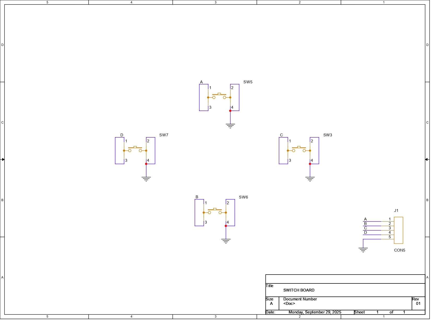
CUSTOM SWITCH PCBThe circuit design for this project was fairly straightforward. The goal was to create a switch PCB featuring four 4×4 tactile push buttons. We began by adding the buttons to the schematic and connecting all four of their pins together, forming a common ground. To simplify wiring, we introduced a CON5 connector, where all button pin 1 terminals were linked along with the shared ground connection.
For the PCB layout, we used the enclosure’s CAD model to define the board outline. The push buttons were placed in their designated positions, and traces were routed from each switch to the CON5 port.
Once the pcb layout was complete, we added custom graphics to the silkscreen layer to enhance the visual appeal of the board and give it a more polished, finished look
PCBWAY SERVICEOnce the board design was finalized, I opted for a purple solder mask with white silkscreen and uploaded the Gerber files to PCBWay’s quote page for fabrication.
While I typically go with a white or black solder mask for most of my builds, this time I decided to try out PCBWay’s Purple option just for a change. The order was placed smoothly, and the PCBs arrived within a week.
The quality was excellent—clean finish, sharp silkscreen, and everything matched the design perfectly.
Over the past ten years, PCBWay has distinguished themselves by providing outstanding PCB manufacturing and assembly services, becoming a trusted partner for countless engineers and designers worldwide.
Also, PCBWay is organizing the PCBWay 8th Project Design Contest, a global event that invites makers, engineers, and innovators to showcase their most creative builds. With categories in Electronics, Mechanical, and AIoT, it’s a great opportunity to share your work, connect with the community, and compete for exciting prizes.
You guys can check out PCBWAY if you want great PCB service at an affordable rate.
SWITCH PCB ASSEMBLY- The switch PCB assembly process starts by placing all the 4x4 through-hole push buttons in their place, then flipping the board over, and then using a soldering iron to secure all components by soldering their pads.
- Next, we added five connecting wires with the CON5 terminal on the backside of the Switch PCB.
- We began the wiring process by adding a CON4 header to the back of the M5Stack AtomS3’s pin header. This connector serves as the interface between the switch PCB and the Atom module.
- Each of the four push button outputs—A, B, C, and D—was carefully soldered to G5, G6, G7, and G8 on the Atom, respectively. The ground pin from the switch PCB was then connected to the GND pin of the Atom to complete the input circuit.
- Next, we wired the speaker, connecting its positive lead to G2 and its negative lead to GND, enabling PWM-based audio output.
- Finally, we connected the lithium cell, which powers the entire device. The positive terminal of the battery was soldered to the 5V pin on the Atom, while the negative terminal was connected to GND, completing the power circuit and making the device fully portable.
Here's the code we used in this project, and it's a simple one; let's have a code breakdown.
#include <Arduino.h>
#include <M5CoreS3.h>
#include <driver/ledc.h>
#include <math.h>
#include <stdlib.h>
// -----------------------------
// Pin Assignments
// -----------------------------
#define BUTTON_A 8   // Kick
#define BUTTON_B 7   // Snare
#define BUTTON_C 6   // Hi-Hat
#define BUTTON_D 5   // Clap
#define SPEAKER_PIN 2  // GPIO 2 for audio
// -----------------------------
// LEDC (PWM audio) Config
// -----------------------------
#define SPEAKER_CHANNEL   LEDC_CHANNEL_0
#define SPEAKER_TIMER     LEDC_TIMER_0
#define SPEAKER_RES       LEDC_TIMER_8_BIT
#define BASE_DUTY 128
// -----------------------------
// Waveform Variables
// -----------------------------
float phase = 0;             // horizontal scroll offset
float waveAmplitude = 5;     // current amplitude
float waveFrequency = 2.0;   // base visual frequency
float targetAmplitude = 5;   // amplitude target
float amplitudeDecay = 0.95; // decay factor per frame
// -----------------------------
// Speaker Setup
// -----------------------------
void setupSpeaker() {
ledc_timer_config_t ledc_timer = {
.speed_mode       = LEDC_LOW_SPEED_MODE,
.duty_resolution  = SPEAKER_RES,
.timer_num        = SPEAKER_TIMER,
.freq_hz          = 2000,
.clk_cfg          = LEDC_AUTO_CLK
};
ledc_timer_config(&ledc_timer);
ledc_channel_config_t ledc_channel = {
.gpio_num       = SPEAKER_PIN,
.speed_mode     = LEDC_LOW_SPEED_MODE,
.channel        = SPEAKER_CHANNEL,
.intr_type      = LEDC_INTR_DISABLE,
.timer_sel      = SPEAKER_TIMER,
.duty           = 0,
.hpoint         = 0
};
ledc_channel_config(&ledc_channel);
}
// -----------------------------
// Drum Sounds
// -----------------------------
void playKick() {
for (int f = 150; f > 50; f -= 5) {
ledc_set_freq(LEDC_LOW_SPEED_MODE, SPEAKER_TIMER, f);
ledc_set_duty(LEDC_LOW_SPEED_MODE, SPEAKER_CHANNEL, BASE_DUTY);
ledc_update_duty(LEDC_LOW_SPEED_MODE, SPEAKER_CHANNEL);
delay(5);
}
ledc_set_duty(LEDC_LOW_SPEED_MODE, SPEAKER_CHANNEL, 0);
ledc_update_duty(LEDC_LOW_SPEED_MODE, SPEAKER_CHANNEL);
}
void playNoise(int duration_ms) {
unsigned long start = millis();
while (millis() - start < duration_ms) {
int val = random(0, 256);
ledc_set_duty(LEDC_LOW_SPEED_MODE, SPEAKER_CHANNEL, val);
ledc_update_duty(LEDC_LOW_SPEED_MODE, SPEAKER_CHANNEL);
delayMicroseconds(50);
}
ledc_set_duty(LEDC_LOW_SPEED_MODE, SPEAKER_CHANNEL, 0);
ledc_update_duty(LEDC_LOW_SPEED_MODE, SPEAKER_CHANNEL);
}
void playSnare() { playNoise(120); }
void playHiHat() { playNoise(50); }
void playClap() {
playNoise(80);
ledc_set_freq(LEDC_LOW_SPEED_MODE, SPEAKER_TIMER, 600);
ledc_set_duty(LEDC_LOW_SPEED_MODE, SPEAKER_CHANNEL, BASE_DUTY);
ledc_update_duty(LEDC_LOW_SPEED_MODE, SPEAKER_CHANNEL);
delay(50);
ledc_set_duty(LEDC_LOW_SPEED_MODE, SPEAKER_CHANNEL, 0);
ledc_update_duty(LEDC_LOW_SPEED_MODE, SPEAKER_CHANNEL);
}
// -----------------------------
// Waveform Visualizer
// -----------------------------
void drawScrollingWave() {
CoreS3.Display.fillScreen(TFT_BLACK);
int width = CoreS3.Display.width();
int height = CoreS3.Display.height();
int midY = height / 2;
for (int x = 0; x < width; x++) {
int y = midY + waveAmplitude * sin((x * waveFrequency * PI / width) + phase);
CoreS3.Display.drawPixel(x, y, TFT_WHITE);
}
phase += 0.2; // scroll wave horizontally
waveAmplitude = waveAmplitude * amplitudeDecay + targetAmplitude * (1.0 - amplitudeDecay);
}
// -----------------------------
// Handle Button Presses
// -----------------------------
void handleButtonPresses() {
if (!digitalRead(BUTTON_A)) { // Kick
playKick();
targetAmplitude += 15;
waveFrequency = 3.0;
}
if (!digitalRead(BUTTON_B)) { // Snare
playSnare();
targetAmplitude += 10;
waveFrequency = 5.0;
}
if (!digitalRead(BUTTON_C)) { // Hi-Hat
playHiHat();
targetAmplitude += 8;
waveFrequency = 7.0;
}
if (!digitalRead(BUTTON_D)) { // Clap
playClap();
targetAmplitude += 12;
waveFrequency = 4.0;
}
if (targetAmplitude > 30) targetAmplitude = 30; // cap amplitude
}
// -----------------------------
// Setup
// -----------------------------
void setup() {
auto cfg = M5.config();
CoreS3.begin(cfg);
setupSpeaker();
pinMode(BUTTON_A, INPUT_PULLUP);
pinMode(BUTTON_B, INPUT_PULLUP);
pinMode(BUTTON_C, INPUT_PULLUP);
pinMode(BUTTON_D, INPUT_PULLUP);
CoreS3.Display.setTextSize(2);
CoreS3.Display.setTextColor(TFT_WHITE, TFT_BLACK);
CoreS3.Display.setTextDatum(middle_center);
CoreS3.Display.fillScreen(TFT_BLACK);
CoreS3.Display.drawString("Drum Pad Ready", CoreS3.Display.width()/2, CoreS3.Display.height()/2);
delay(1000);
}
// -----------------------------
// Main Loop
// -----------------------------
void loop() {
handleButtonPresses();
drawScrollingWave();
delay(30); // adjust speed of wave
}
We first start by including the necessary libraries we need in this project.
#include <Arduino.h>
#include <M5CoreS3.h>
#include <driver/ledc.h>
#include <math.h>
#include <stdlib.h>
Next we define which GPIO pins are connected to which components.
#define BUTTON_A 8   // Kick drum trigger
#define BUTTON_B 7   // Snare trigger
#define BUTTON_C 6   // Hi-Hat trigger
#define BUTTON_D 5   // Clap trigger
#define SPEAKER_PIN 2  // Audio output via PWM
This sets up the ESP32’s PWM system to generate tones.
#define SPEAKER_CHANNEL   LEDC_CHANNEL_0
#define SPEAKER_TIMER     LEDC_TIMER_0
#define SPEAKER_RES       LEDC_TIMER_8_BIT
#define BASE_DUTY         128  // 50% duty cycle for square wave
These control the behavior of the scrolling waveform.
float phase = 0;             // Horizontal scroll offset
float waveAmplitude = 5;     // Current amplitude of the waveform
float waveFrequency = 2.0;   // Base frequency of the waveform
float targetAmplitude = 5;   // Target amplitude after a drum hit
float amplitudeDecay = 0.95; // Smooth decay toward idle waveform
The Speaker Setup function configures the PWM timer and channel for audio output.
void setupSpeaker() {
  // Sets frequency, resolution, and clock source
  ledc_timer_config_t ledc_timer = { ... };
  ledc_timer_config(&ledc_timer);

  // Assigns GPIO pin and links it to the timer
  ledc_channel_config_t ledc_channel = { ... };
  ledc_channel_config(&ledc_channel);
}
Now comes the Drum Sound Function part.
Kick: Descending pitch sweep for a punchy thump
Snare/Hi-Hat: White noise bursts using random duty cycles.
Clap: A Noise burst followed by a short tone.
void playKick() { ... }
void playNoise(int duration_ms) { ... }
void playSnare() { playNoise(120); }
void playHiHat() { playNoise(50); }
void playClap() { ... }
This is the Waveform Visualizer section that draws a scrolling sine wave that reacts to drum hits.
void drawScrollingWave() {
  CoreS3.Display.fillScreen(TFT_BLACK);
  for (int x = 0; x < width; x++) {
    int y = midY + waveAmplitude * sin(...);
    CoreS3.Display.drawPixel(x, y, TFT_WHITE);
  }
  phase += 0.2;
  waveAmplitude = waveAmplitude * amplitudeDecay + targetAmplitude * (1.0 - amplitudeDecay);
}
Button Handling—This section checks each button and triggers the corresponding sound and waveform boost.
void handleButtonPresses() {
  if (!digitalRead(BUTTON_A)) { playKick(); ... }
  if (!digitalRead(BUTTON_B)) { playSnare(); ... }
  if (!digitalRead(BUTTON_C)) { playHiHat(); ... }
  if (!digitalRead(BUTTON_D)) { playClap(); ... }
}
In Setup Function we initialize the display, speaker, and buttons.
void setup() {
  CoreS3.begin(cfg);
  setupSpeaker();
  pinMode(...) for all buttons;
  Display splash: "Drum Pad Ready"
}
At last we have a very simple loop function that continuously checks for input and updates the waveform.
void loop() {
  handleButtonPresses();
  drawScrollingWave();
  delay(30); // Controls visual refresh rate
}- Assembly begins by placing all the 3D-printed switch actuators into their designated slots from the inside of the front enclosure.
- Next, the M5Stack Atom is inserted into its position within the front enclosure—this section is held securely with a pressure fit.
- Following that, the switch PCB is aligned with the screw bosses inside the enclosure and fastened using four M2 screws.
- The battery is then placed directly over the switch PCB within the enclosure.
- Finally, the back enclosure is positioned from the rear and secured to the front using four M2.5 Torx screws, completing the full device assembly.
Here’s the end result of this small build—a HitPad. Compact, responsive, and fun to use, it delivers exactly what I set out to create: a pocket-sized tone generator that’s easy to carry and satisfying to play.
I added an ID card strap to the provided hook on the enclosure, which lets me wear it around my neck just like a badge. This makes it super convenient to play on the go—whether I’m walking around, waiting somewhere, or just passing time.
Thanks to its onboard 600 mAh lithium-ion cell, HitPad offers up to 5 hours of continuous use, making the entire device completely wireless. No cables, no external power—just tap and play wherever you are.
For now this project has been completed.
Thanks for reaching this far, and I will be back with a new project pretty soon.
Peace.


_t9PF3orMPd.png?auto=compress%2Cformat&w=40&h=40&fit=fillmax&bg=fff&dpr=2)


Comments