



Hardware components | ||||||
| × | 1 | ||||
 |
| × | 1 | |||
Software apps and online services | ||||||
 |
| |||||
 |
| |||||
Hand tools and fabrication machines | ||||||
 |
| |||||
Greetings everyone, and welcome back. Here's something fun and custom.
This is my version of an Xbox controller, which I built from scratch. It features an ESP32-C6 DevKit as the main MCU, paired with custom button boards, analog joysticks, and a custom-designed body to create a DIY Xbox wireless controller.
Using this controller is just like using any Xbox controller; we simply pair it with Bluetooth, open Steam, assign the button mapping, and play games with it.
For the demo, I tried playing Broforce and Fallout: New Vegas, and both of them worked well.
This article covers the complete build process of this project. Let’s get started with the build.
MATERIALS REQUIREDThese were the components used in this project
- Custom PCBs (Provided by PCBWAY)
- ESP32 C6 DEV Kit V1
- 4x4 Tacktile switches
- 12x12 Tacktiole switch
- M2 screws
- Analog Jyostick breakout board
- 3.7V 500mAh 14500 Li-ion Cell
- PCM Module
- Handheld Tig welder
- 3D Printed parts
For the design of our controller, I wanted something simple that follows the Xbox controller button layout. I kept the button layout mostly the same, but changed the overall shape from a traditional controller design to a rounded cuboid shape with a curved back. The design is minimal, and for aesthetics, I planned to print the parts in two colors.
The entire design was created in Autodesk Fusion 360.
PARTSWe began the design process by arranging all the hardware, such as the ESP32 board, analog sticks, switch PCBs, and lithium cell, in a layout similar to a regular Xbox controller. The button and joystick placement closely followed the Xbox controller layout, while the rest of the components were positioned wherever they fit best inside the design.
Based on this arrangement, the outer shell was designed around the components.
XBOX BUTTON SUDO PCBNow here’s a clever hack: did you know you can 3D print your own PCB? Well, not a complete PCB, but a board that can hold through-hole components in place. That’s exactly how I modeled the Xbox button PCB.
For this, I placed a 12×12 push button onto the design and added four mounting holes for the switch leads, along with two additional holes for mounting the board to the controller body.
The idea here is to print this board using regular PLA, place the switch onto it, and let the switch leads hold everything in place. Then, during wiring, we directly solder wires to the leads of the switch. This “PCB” only acts as a holder that keeps the switch securely positioned.
3D PRINTED PARTSThe front and back body parts were printed in black PLA, while all the buttons were printed in red PLA to create a dual-tone red-and-black color effect.
Here, we used HYPE PLA red and black filament for all the prints. All parts were printed at a 0.2mm layer height using a 0.4mm nozzle with 15% infill.
HARDWAREThe hardware used in this project was fairly simple. We used an ESP32-C6 DevKit as the main controller, which provides plenty of GPIO pins, most of which are utilized in this build.
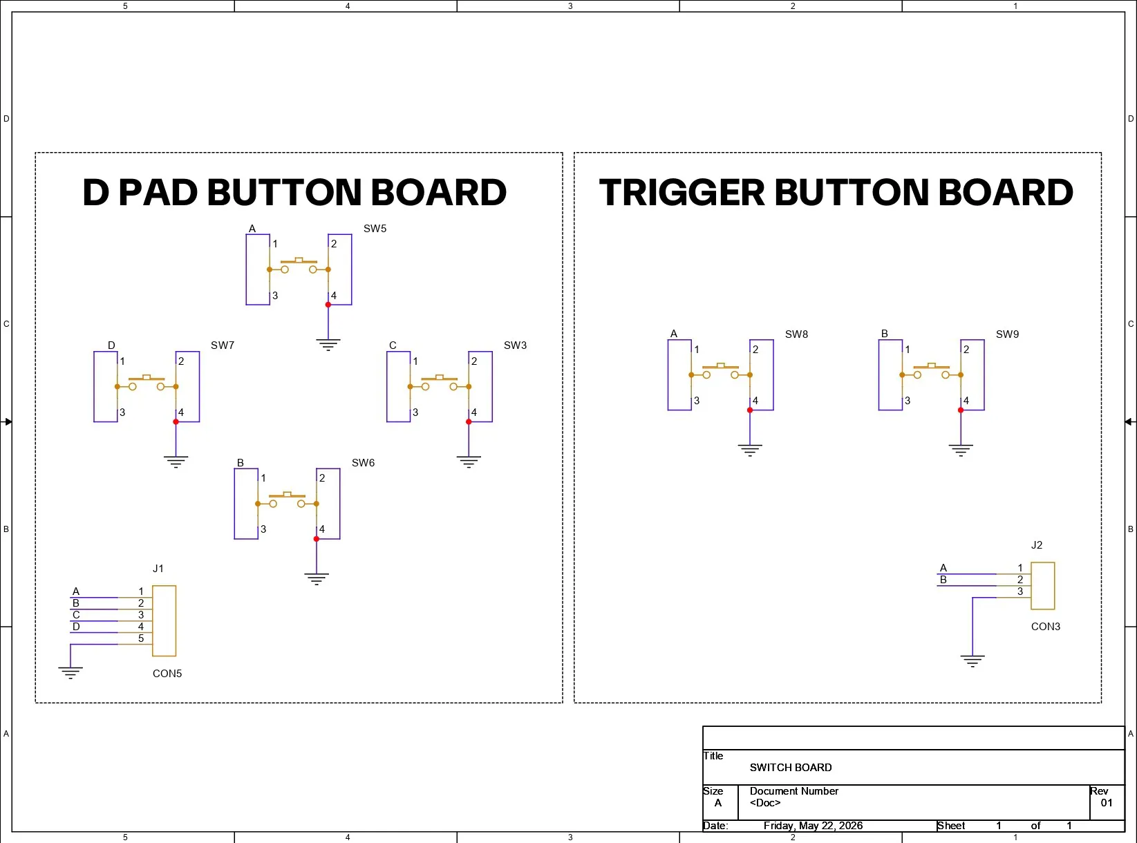
We also prepared custom D-pad and trigger button PCBs, which are used as button input boards.
For the analog controls, we used generic analog joysticks that I got from Amazon. These are used as the left and right analog sticks for the controller.
PCB SWITCH BOARDFor the PCB design of this project, I’m using two button boards that I designed specifically for projects like this, where I need to add button functionality. The idea is simple: place multiple buttons on a PCB, connect one side of all the buttons to GND, and route the other side to a connector that can be interfaced with a microcontroller for button input.
These boards are mainly intended for proof-of-concept builds like this one. The board layout, outline, and push-button positions were all designed by following the CAD file dimensions of both switch boards.
PCB ASSEMBLYThe assembly process for these two button boards was also simple. The only component required was a 4×4 push switch. For our build, we needed two four-button boards and two double-button boards, making a total of 12 buttons. Each button was placed one by one into its designated position on all four boards.
After that, each board was flipped over, and we used a soldering iron to permanently secure all the switches in place, completing the button board assembly process.
POWER SOURCE ASSEMBLYFor the power source of our controller, we wanted to use something smaller than regular 18650 cells. Using a LiPo battery was one option, but they don’t have enough capacity to power our device for hours of gameplay.
Instead, we decided to use a lithium-ion cell in a different form factor. We selected a 14500 cell, which is essentially a smaller version of a 18650 cell with roughly half the capacity.
Here, we are using a 3.7V 500mAh Li-ion cell.
The cell comes bare, without any PCM circuit. A PCM circuit is mandatory when a lithium cell is being used alone without any dedicated charging/discharging circuitry. What this PCM does is provide low-cut, high-cut, and short-circuit protection functions that protect the cell and make sure it doesn’t explode like a firecracker.
For adding the PCM to the cell, I used a new tool in my arsenal: a handheld TIG welder. This is an extremely helpful tool while working with cells because it ensures we don’t directly touch the lithium cell terminals with a soldering iron. Touching the terminals with a hot soldering iron can degrade the cell and reduce its capacity.
Here’s how we made the connections between the PCM and the cell:
- The PCM comes pre-soldered with two nickel strips. We placed the PCM with the cell and cut off the excess length of the nickel strips.
- Then we bent the strips by aligning them with the cell terminals. Using the TIG welder, we spot-welded the nickel strip to the positive terminal first. We did two to three weld points for a stronger connection.
- After that, we turned the cell over and repeated the same process for the negative terminal.
- Once the connections were done, we added wires to the P+ and P− terminals of the PCM, then used a multimeter to make sure we were getting an output voltage. This confirmed that our cell was working properly.
Here’s why this PCM is important: we will be connecting this cell to the 5V input of an ESP32 DevKit. This means that when we plug a Type-C cable into the ESP32, the cell will start charging from 5V. But if the cell voltage goes above 4.2V, the cell could potentially go boom. The PCM prevents this from happening. When the voltage reaches 4.2V, it cuts the connection between B+ and P+, stopping the charging process.
The same goes for low-voltage protection. The PCM cuts the power when the cell reaches around 2.2V, which is the recommended lower discharge limit.
I have also prepared a video showing the construction process of this part, which you can watch.
FRONT BODY ASSEMBLYWe began the assembly process by placing the D-pad button and XYAB buttons into their positions from the inside of the front body.
Next, the button boards were placed over the D-pad and XYAB buttons and aligned with the screw bosses. We then used four M2 screws for each PCB to secure them in place.
Similarly, the analog joystick modules were positioned over their mounting locations and secured using M2 screws. We used washer-head screws here to keep the joystick modules firmly in place.
XBOX BUTTON SUDO PCB ASSEMBLYThe Xbox button was positioned in place, and over that, we placed the 3D-printed switch PCB. After aligning it with the two mounting screw bosses, we used two M2 screws to secure it in place.
SHOULDER & TRIGGER BUTTON PCBThe button boards for the trigger and shoulder buttons were positioned in place.
We modeled two retaining ribs into the top body, allowing the PCBs to easily slide into them and stay securely pressure-fitted in place.
WIRINGThe wiring process for this setup was quite easy and straightforward. For wiring, we needed a lot of jumper wires. I used single-core silver-coated copper wire because it connects well with solder pads, and since it is single-core, we don’t run into issues where a single strand fails to solder properly and accidentally shorts the connector next to it.
We began by connecting the GND of all the button boards and both analog sticks to the GND pin of the ESP32-C6 DevKit.
Next, the 3V3 pin of the ESP32 was connected to the VCC pins of both analog joysticks.
Connections
- Left Analog Stick X to GPIO0
- Left Analog Stick Y to GPIO1
- Right Analog Stick X to GPIO2
- Right Analog Stick Y to GPIO3
Button Connections
- GPIO10 to A Button
- GPIO11 to B Button
- GPIO13 to X Button
- GPIO18 to Y Button
- GPIO15 to LB Button
- GPIO23 to RB Button
- GPIO6 to Left Stick Click (LS Click)
- GPIO7 to Right Stick Click (RS Click)
- GPIO8 to Xbox Guide / Home Button
Here's the code I prepared for this project, and it's a simple one.
#include <BleGamepad.h>
// Initialize BLE Gamepad as Xbox Controller
BleGamepad bleGamepad("Xbox Wireless Controller", "Microsoft", 100);
// ESP32-C6 Analog Pin Mapping (Joysticks Only)
#define LEFT_STICK_X 0
#define LEFT_STICK_Y 1
#define RIGHT_STICK_X 2
#define RIGHT_STICK_Y 3
// Digital Buttons Configuration (Pin, BLE ID)
struct ButtonMapping {
uint8_t pin;
uint16_t gamepadButton;
};
// Your precise working layout
ButtonMapping actionButtons[] = {
{10, BUTTON_1},  // A
{11, BUTTON_2},  // B
{13, BUTTON_3},  // X
{18, BUTTON_4},  // Y
{15, BUTTON_5},  // LB
{23, BUTTON_6},  // RB
{6,  BUTTON_9},  // LS Click
{7,  BUTTON_10}, // RS Click
{8,  BUTTON_13}  // Xbox Guide / Home Button
};
const int numButtons = sizeof(actionButtons) / sizeof(ButtonMapping);
// Trigger Buttons
#define LEFT_TRIGGER_BTN 4
#define RIGHT_TRIGGER_BTN 5
// D-Pad Pin Assignments
#define DPAD_U 19
#define DPAD_D 20
#define DPAD_L 21
#define DPAD_R 22
void setup() {
Serial.begin(115200);
pinMode(LEFT_STICK_X, INPUT);
pinMode(LEFT_STICK_Y, INPUT);
pinMode(RIGHT_STICK_X, INPUT);
pinMode(RIGHT_STICK_Y, INPUT);
for (int i = 0; i < numButtons; i++) {
pinMode(actionButtons[i].pin, INPUT_PULLUP);
}
pinMode(LEFT_TRIGGER_BTN, INPUT_PULLUP);
pinMode(RIGHT_TRIGGER_BTN, INPUT_PULLUP);
pinMode(DPAD_U, INPUT_PULLUP);
pinMode(DPAD_D, INPUT_PULLUP);
pinMode(DPAD_L, INPUT_PULLUP);
pinMode(DPAD_R, INPUT_PULLUP);
// Configure BLE Gamepad reports
BleGamepadConfiguration bleGamepadConfig;
bleGamepadConfig.setAutoReport(false);
bleGamepadConfig.setWhichAxes(true, true, true, true, true, true, false, false);
bleGamepad.begin(&bleGamepadConfig);
Serial.println("ESP32-C6 Joystick Precision Patch Loaded!");
}
void loop() {
if (bleGamepad.isConnected()) {
// 1. Process Action & Xbox Guide buttons
for (int i = 0; i < numButtons; i++) {
if (digitalRead(actionButtons[i].pin) == LOW) {
bleGamepad.press(actionButtons[i].gamepadButton);
} else {
bleGamepad.release(actionButtons[i].gamepadButton);
}
}
// 2. Process Digital Triggers
if (digitalRead(LEFT_TRIGGER_BTN) == LOW) {
bleGamepad.setLeftTrigger(65535);
} else {
bleGamepad.setLeftTrigger(0);
}
if (digitalRead(RIGHT_TRIGGER_BTN) == LOW) {
bleGamepad.setRightTrigger(65535);
} else {
bleGamepad.setRightTrigger(0);
}
// 3. Process D-Pad Vectors
bool up = (digitalRead(DPAD_U) == LOW);
bool down = (digitalRead(DPAD_D) == LOW);
bool left = (digitalRead(DPAD_L) == LOW);
bool right = (digitalRead(DPAD_R) == LOW);
if (up && right) bleGamepad.setHat1(DPAD_UP_RIGHT);
else if (down && right) bleGamepad.setHat1(DPAD_DOWN_RIGHT);
else if (down && left) bleGamepad.setHat1(DPAD_DOWN_LEFT);
else if (up && left) bleGamepad.setHat1(DPAD_UP_LEFT);
else if (up) bleGamepad.setHat1(DPAD_UP);
else if (down) bleGamepad.setHat1(DPAD_DOWN);
else if (left) bleGamepad.setHat1(DPAD_LEFT);
else if (right) bleGamepad.setHat1(DPAD_RIGHT);
else bleGamepad.setHat1(HAT_CENTERED);
// 4. Process Joysticks
// OPTIMIZED: Re-scaled to standard signed integer limits to eliminate the floating center issue.
// Note: If an axis moves opposite to your hand, swap the last two numbers (e.g., -32767, 32767 to 32767, -32767)
int lsX = map(analogRead(LEFT_STICK_Y), 0, 4095, -32767, 32767);
int lsY = map(analogRead(LEFT_STICK_X), 0, 4095, -32767, 32767);
int rsX = map(analogRead(RIGHT_STICK_X), 0, 4095, -32767, 32767);
int rsY = map(analogRead(RIGHT_STICK_Y), 0, 4095, -32767, 32767);
bleGamepad.setLeftThumb(lsX, lsY);
bleGamepad.setRightThumb(rsX, rsY);
// Send unified controller state data
bleGamepad.sendReport();
delay(8);
}
}
What our sketch does is transform the ESP32-C6 DevKit into a fully functional wireless game controller. For this, we used the BleGamepad library, which emulates a standard plug-and-play Xbox-style wireless controller over HID via Bluetooth.
We uploaded the code to our ESP32-C6 DevKit, and after uploading, the device appeared as a Bluetooth game controller when searched for on a computer. We connected to it and then opened the Gamepad Tester website, which is a great tool for testing wired and wireless controllers.
Whenever we pressed a button or moved a joystick, we could see it being displayed as a button input or axis movement, confirming that the setup was working correctly.
FINAL ASSEMBLYWe began the final assembly process by connecting the lithium cell’s positive and negative terminals to the ESP32-C6’s 5V and GND pins.
The ESP32-C6 board was then placed into its designated position inside the back body and secured in place using a hot glue gun.
Next, the shoulder and trigger buttons were installed into both the front and back body sections. After that, both halves of the body were fitted together, and four M2 screws were used to secure everything in place, completing the assembly process.
Our controller was now complete.
RESULT
Here’s the end result of our build: an Xbox controller that works with both Windows and Mac. It should even work with Linux, although I haven’t tested that yet.
To pair the controller, we go into the Bluetooth settings, where our device shows up as a “Wireless Controller.” We pair the device and open Gamepad Tester, which is a really good web-based gamepad testing tool. By moving the analog sticks and pressing buttons, we can see all the inputs being registered, which confirms that the setup is working perfectly.
Next, we open Steam. Since this controller does not use XInput directly out of the box and instead works as a wireless HID controller, we first need to map the buttons manually. We go into the controller settings in Steam and assign each button one by one, skipping the ones we don’t have, which in our case were only two buttons.
Once the mapping is done, anytime we pair the controller with Steam, it just works. Double-pressing the Steam button on the controller even makes Steam enter Big Picture Mode.
Using this controller, we tested two games: Broforce and Fallout: New Vegas. I did notice some input lag in the left and right analog sticks, but aside from that, everything seemed to function properly.
Now, here’s the problem with my design: it’s not better than the Xbox controller.
Sure, it works, but it doesn’t even feel like a cheap commercial controller. It feels very DIY, and honestly, that’s completely fine because it has its own advantages. One of the biggest advantages is that anyone can build one and customize it according to their own requirements. It’s also open-source, unlike most commercial controllers.
This project was more of a proof of concept. In the future, I’ll be preparing a simplified version that reduces the wiring and puts everything onto a single board. Instead of using an ESP32 DevKit, the ESP32 chip itself could be used directly. Higher-quality joysticks and better buttons could also be added. There’s a lot of room for improvement.
For now, this project has been completed. Special thanks for reaching this far, and I’ll be back with a new project very soon.


_t9PF3orMPd.png?auto=compress%2Cformat&w=40&h=40&fit=fillmax&bg=fff&dpr=2)


Comments