


Hardware components | ||||||
_ztBMuBhMHo.jpg?auto=compress%2Cformat&w=48&h=48&fit=fill&bg=ffffff) |
| × | 1 | |||
| × | 1 | ||||
| × | 1 | ||||
| × | 1 | ||||
Hand tools and fabrication machines | ||||||
 |
| |||||
- Download one or all of these FreeCAD templates (tree, heart or star) and export them as STL-files. Or download the STL-files here.
- Export it by clicking on the object in the feature tree on the left side of the FreeCAD and then choosing export in the file-menu. Choose the file format STL, which is part of the Mesh-formats group that you can choose under file-formats in the export panel.
OR
- You could make them yourself in FreeCAD.
- Make a new sketch, draw your symbol, exit the sketch and “pad” it. A good thickness is 2 mm. But you can make it thicker if you want.
- Make a new sketch on the top face of the shape you just made. Draw a square with the dimensions: 5.2 mm x 5.2 mm.
- Exit the Square sketch and make a “pocket” straight through the first shape you made (the heart, tree or something else). You can set the pocket type to “through all”.
- Make indentations in the first shape to make room for the resistors and capacitors on the LED PCB. A good depth for this pocket is 0.8 mm. Set the pocket type to “Dimension”.
- OPTIONAL: If you feel like it, you can add a chamfer or fillet around the edges of your symbol. You do this by clicking the edges of the object and the clicking the chamfer or fillet button in tool-bar or in the “task” tab on the left side of the screen.
- Open Slic3r and drag one of the STL-files to the print area in the “
Plater” tab.
- Import the settings like we discussed in the previous tutorials (LINK), choosing “
Load config” in the file-menu of Slic3r” and opening yoursettings-ini-file.
- Use these settings to print as many of the LED holders as you want.
NOTE: Go through this checklist once in a while before printing:
- Turn ON 3D printer. Check that ac-adapter is plugged in.
- Check that build area is completely flat and free of dirt/debris.
- Calibrate 3D printer platform height relative to the extruder nozzle (level the bed).
- Check there is enough material for the size of object you are printing.
- Check that the material is extruding correctly through the nozzle.
- Download the template for the box here and open it in FreeCAD. Or downoad the STL-file here (if you download it here, you can skip the next step).
- Export it by clicking on the object in the feature tree on the left side of FreeCAD and then choosing export in the file-menu.
- Open Slic3r and drag the STL file to the print surface in Slic3r.
- Export the Gcode to a SD-card and insert the card into the printers card reader.
- Remove the support material from the box to make it usable. Be careful, if you use a sharp knife to do this. I find it useful to use a scalpel and a pair of pliers.
- Download the STL-file of the lid or export and STL from this FreeCAD file
- Use the same settings as you used for the symbols. Notice that we don’t need support for the flat objects with little or none protruding edges.
- The lid snaps into the inner sides of the box with the help of small indentations on the box and edges on the lid.
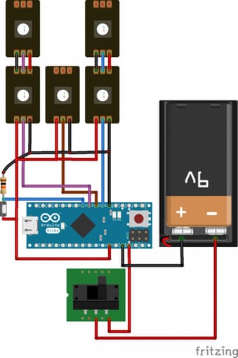
In this project, we’ll use an Arduino Micro to control 5 WS2812 Addressable LEDs, cycling through different stages by pressing a push button.
Schematic for the circuit below.
5. Solder the cables to the LEDs- Braid the cables, to make them look nice.
- TIP!: Braiding them first and soldering them afterwards makes it easier to keep the wires in place.
- Solder the wires to the LEDs. There are three connectors on each side of the LED: One plus one.
- TIP!: Using solder paste is easier than using soldering wire.
NOTE: I used a white cables to make my braided wires look nice. But feel free to use what ever color you like. If you use the same color for all the wires, use a multimeter to tell the cables from each other.
6. Attach the battery connector to the Arduino MicroIf you'd like, you can change the wire on the battery connector to colors that you find more suitable than the standard black ones.
We will use Adafruit’s Neopixel Library to control the LEDs. The code is very similar to one of the examples provided in the Neopixel library, we just need to change some declarations and add two more strips
objects.
- Upload the Sketch using the Arduino IDE Now the Arduino will get power from the computer USB, but if you have connected the ground and 5V in the wrong way the Arduino will not light up. In that case, just switch them around and the Arduino should light up.


Comments