


Hardware components | ||||||
_ztBMuBhMHo.jpg?auto=compress%2Cformat&w=48&h=48&fit=fill&bg=ffffff) |
| × | 1 | |||
| × | 1 | ||||
| × | 1 | ||||
Before continuing with this lesson please follow this getting started guide.
2. How does it work?The provided code is based on the BLEControllerSketch that you can find in RBL_nRF8001 -> BLEControllerSketch.
The original sketch allows you to modify and interact with all the Arduino's pins, but it has been modified in a way that you cannot modify pins used by the modified sketch it self.
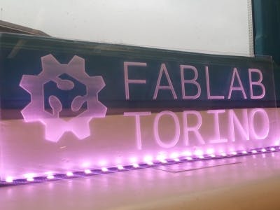
This modified sketch in fact allows you to drive a WS2812 LED strip using your smartphone as remote controller! In this way you can make for example a light banner to put in your shop! Change the color of your banner whenever you want in a very easy way!
From the smartphone interface you can see that pin 3, 5 and 6 are set as PWM (and you cannot change their status as INPUT, OUTPUT or SERVO) while pin 9 is totally missing from the list. In fact they are used by the sketch so in order to avoid conflicts these functionalities are disabled. This means that using this sketch you can do a lot of other things than simply control lights!
ATTENTION: The added parts of code are identified by the comments:
/*______________Mods to use it as light controller____________*/
....
....
....
....
/*____________________________________________________________*/
The light is controlled by the slide bars on the interface. In particular:
1) pin 3 control the amount of RED;
2) pin 5 control the amount of GREEN;
3) pin 6 control the amount of BLUE;
As you can see in the code the EEPROM library is used. In this way when you power off the board your previous settings can be stored. In fact at the startup the variables redValue
, greenValue
and blueValue
are initialized reading the EEPROM (locations 0, 1 and 2 respectively).
 case 'N': // set PWM
      {
        byte pin = ble_read();
        byte value = ble_read();
        /*______________Mods to use it as light controller____________*/
        if(pin == RED)
        {
          redValue = value;
          EEPROM.write(0, redValue);
        }
        if(pin == GREEN)
        {
          greenValue = value;
          EEPROM.write(1, greenValue);
        }
        if(pin == BLUE)
        {
          blueValue = value;
          EEPROM.write(2, blueValue);
        }
        if (pin == LEDsPin || pin == RED || pin == GREEN || pin == BLUE) //refresh the light only if something change
        {
          for (int i = 0; i < NUMPIXELS; i++) {
            // pixels.Color takes RGB values, from 0,0,0 up to 255,255,255
            pixels.setPixelColor(i, pixels.Color(redValue, greenValue, blueValue));
            pixels.show(); // This sends the updated pixel color to the hardware.
            delayMicroseconds(500); // Delay for a period of time
          }
        }
        /*____________________________________________________________*/
        analogWrite(PIN_TO_PWM(pin), value);
        pin_pwm[pin] = value;
        reportPinPWMData(pin);
      }
      break;
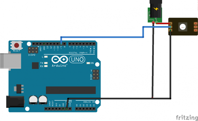
Here the full code and the layout. It is suggested to download the code (see attachments) instead of cut and paste it because another file is needed.
WARNING: Please use an external 5V power supply to supply the WS2812 as indicated in the layout.
/*
 Copyright (c) 2012, 2013 RedBearLab
 Permission is hereby granted, free of charge, to any person obtaining a copy of this software and associated documentation files (the "Software"), to deal in the Software without restriction, including without limitation the rights to use, copy, modify, merge, publish, distribute, sublicense, and/or sell copies of the Software, and to permit persons to whom the Software is furnished to do so, subject to the following conditions:
 The above copyright notice and this permission notice shall be included in all copies or substantial portions of the Software.
 THE SOFTWARE IS PROVIDED "AS IS", WITHOUT WARRANTY OF ANY KIND, EXPRESS OR IMPLIED, INCLUDING BUT NOT LIMITED TO THE WARRANTIES OF MERCHANTABILITY, FITNESS FOR A PARTICULAR PURPOSE AND NONINFRINGEMENT. IN NO EVENT SHALL THE AUTHORS OR COPYRIGHT HOLDERS BE LIABLE FOR ANY CLAIM, DAMAGES OR OTHER LIABILITY, WHETHER IN AN ACTION OF CONTRACT, TORT OR OTHERWISE, ARISING FROM, OUT OF OR IN CONNECTION WITH THE SOFTWARE OR THE USE OR OTHER DEALINGS IN THE SOFTWARE.
 modified on 01/12/2014 by
 Arturo Guadalupi
 <a.guadalupi@arduino.cc>
 */
#include <Servo.h>
#include <SPI.h>
#include <boards.h>
#include <RBL_nRF8001.h>
#include <services.h>
#include "Boards.h"
/*______________Mods to use it as light controller____________*/
#include <Adafruit_NeoPixel.h>
#include <EEPROM.h>  //EEPROM is used to store user's value in order to have the chosen light at startup
/*____________________________________________________________*/
#define PROTOCOL_MAJOR_VERSION   0 //
#define PROTOCOL_MINOR_VERSION   0 //
#define PROTOCOL_BUGFIX_VERSION  2 // bugfix
#define PIN_CAPABILITY_NONE      0x00
#define PIN_CAPABILITY_DIGITAL   0x01
#define PIN_CAPABILITY_ANALOG    0x02
#define PIN_CAPABILITY_PWM       0x04
#define PIN_CAPABILITY_SERVO     0x08
#define PIN_CAPABILITY_I2C       0x10
// pin modes
//#define INPUT                 0x00 // defined in wiring.h
//#define OUTPUT                0x01 // defined in wiring.h
#define ANALOG                  0x02 // analog pin in analogInput mode
#define PWM                     0x03 // digital pin in PWM output mode
#define SERVO                   0x04 // digital pin in Servo output mode
byte pin_mode[TOTAL_PINS];
byte pin_state[TOTAL_PINS];
byte pin_pwm[TOTAL_PINS];
byte pin_servo[TOTAL_PINS];
Servo servos[MAX_SERVOS];
/*______________Mods to use it as light controller____________*/
const int RED = 3;
const int GREEN = 5;
const int BLUE = 6;
const int NUMPIXELS = 60;
const int LEDsPin = 9;    // LEDs connected to digital pin 9
int redValue = 0, greenValue = 0, blueValue = 0;
Adafruit_NeoPixel pixels = Adafruit_NeoPixel(NUMPIXELS, LEDsPin, NEO_GRB + NEO_KHZ800);
/*____________________________________________________________*/
void setup()
{
  Serial.begin(57600);
  Serial.println("BLE Arduino Slave");
  /* Default all to digital input */
  for (int pin = 0; pin < TOTAL_PINS; pin++)
  {
    /*______________Mods to use it as light controller____________*/
    if (pin == LEDsPin || pin == RED || pin == GREEN || pin == BLUE)  //these pin are needed for the project and we don't want to change them
      pin++;                                                          //skip them
    /*____________________________________________________________*/
    // Set pin to input with internal pull up
    pinMode(pin, INPUT);
    digitalWrite(pin, HIGH);
    // Save pin mode and state
    pin_mode[pin] = INPUT;
    pin_state[pin] = LOW;
  }
  // Default pins set to 9 and 8 for REQN and RDYN
  // Set your REQN and RDYN here before ble_begin() if you need
  //ble_set_pins(3, 2);
  // Set your BLE Shield name here, max. length 10
  //ble_set_name("My Name");
  // Init. and start BLE library.
  ble_begin();
  /*______________Mods to use it as light controller____________*/
  pinMode(RED, OUTPUT);
  pinMode(GREEN, OUTPUT);
  pinMode(BLUE, OUTPUT);
  pinMode(LEDsPin, OUTPUT);
  redValue = EEPROM.read(0);
  greenValue = EEPROM.read(1);
  blueValue = EEPROM.read(2);
  pin_pwm[RED] = redValue;
  reportPinPWMData(RED);
  pin_mode[RED] = PWM;
  pin_pwm[GREEN] = greenValue;
  reportPinPWMData(GREEN);
  pin_mode[GREEN] = PWM;
  pin_pwm[BLUE] = blueValue;
  reportPinPWMData(BLUE);
  pin_mode[BLUE] = PWM;
  pin_mode[LEDsPin] = OUTPUT;
  for (int i = 0; i < NUMPIXELS; i++) {
    // pixels.Color takes RGB values, from 0,0,0 up to 255,255,255
    pixels.setPixelColor(i, pixels.Color(redValue, greenValue, blueValue));
    pixels.show(); // This sends the updated pixel color to the hardware.
    delayMicroseconds(500); // Delay for a period of time
  }
  /*____________________________________________________________*/
}
static byte buf_len = 0;
void ble_write_string(byte *bytes, uint8_t len)
{
  if (buf_len + len > 20)
  {
    for (int j = 0; j < 15000; j++)
      ble_do_events();
    buf_len = 0;
  }
  for (int j = 0; j < len; j++)
  {
    ble_write(bytes[j]);
    buf_len++;
  }
  if (buf_len == 20)
  {
    for (int j = 0; j < 15000; j++)
      ble_do_events();
    buf_len = 0;
  }
}
byte reportDigitalInput()
{
  if (!ble_connected())
    return 0;
  static byte pin = 0;
  byte report = 0;
  if (!IS_PIN_DIGITAL(pin))
  {
    pin++;
    if (pin >= TOTAL_PINS)
      pin = 0;
    return 0;
  }
  if (pin_mode[pin] == INPUT)
  {
    byte current_state = digitalRead(pin);
    if (pin_state[pin] != current_state)
    {
      pin_state[pin] = current_state;
      byte buf[] = {
        'G', pin, INPUT, current_state                                                };
      ble_write_string(buf, 4);
      report = 1;
    }
  }
  pin++;
  if (pin >= TOTAL_PINS)
    pin = 0;
  return report;
}
void reportPinCapability(byte pin)
{
  byte buf[] = {
    'P', pin, 0x00                };
  byte pin_cap = 0;
  if (IS_PIN_DIGITAL(pin))
    pin_cap |= PIN_CAPABILITY_DIGITAL;
  if (IS_PIN_ANALOG(pin))
    pin_cap |= PIN_CAPABILITY_ANALOG;
  if (IS_PIN_PWM(pin))
    pin_cap |= PIN_CAPABILITY_PWM;
  if (IS_PIN_SERVO(pin))
    pin_cap |= PIN_CAPABILITY_SERVO;
  buf[2] = pin_cap;
  ble_write_string(buf, 3);
}
void reportPinServoData(byte pin)
{
  //  if (IS_PIN_SERVO(pin))
  //    servos[PIN_TO_SERVO(pin)].write(value);
  //  pin_servo[pin] = value;
  byte value = pin_servo[pin];
  byte mode = pin_mode[pin];
  byte buf[] = {
    'G', pin, mode, value                };
  ble_write_string(buf, 4);
}
byte reportPinAnalogData()
{
  if (!ble_connected())
    return 0;
  static byte pin = 0;
  byte report = 0;
  if (!IS_PIN_DIGITAL(pin))
  {
    pin++;
    if (pin >= TOTAL_PINS)
      pin = 0;
    return 0;
  }
  if (pin_mode[pin] == ANALOG)
  {
    uint16_t value = analogRead(pin);
    byte value_lo = value;
    byte value_hi = value>>8;
    byte mode = pin_mode[pin];
    mode = (value_hi << 4) | mode;
    byte buf[] = {
      'G', pin, mode, value_lo                                };
    ble_write_string(buf, 4);
  }
  pin++;
  if (pin >= TOTAL_PINS)
    pin = 0;
  return report;
}
void reportPinDigitalData(byte pin)
{
  byte state = digitalRead(pin);
  byte mode = pin_mode[pin];
  byte buf[] = {
    'G', pin, mode, state                };
  ble_write_string(buf, 4);
}
void reportPinPWMData(byte pin)
{
  byte value = pin_pwm[pin];
  byte mode = pin_mode[pin];
  byte buf[] = {
    'G', pin, mode, value                };
  ble_write_string(buf, 4);
}
void sendCustomData(uint8_t *buf, uint8_t len)
{
  uint8_t data[20] = "Z";
  memcpy(&data[1], buf, len);
  ble_write_string(data, len+1);
}
byte queryDone = false;
void loop()
{
  while(ble_available())
  {
    byte cmd;
    cmd = ble_read();
    Serial.write(cmd);
    // Parse data here
    switch (cmd)
    {
    case 'V': // query protocol version
      {
        byte buf[] = {
          'V', 0x00, 0x00, 0x01                                                                };
        ble_write_string(buf, 4);
      }
      break;
    case 'C': // query board total pin count
      {
        byte buf[2];
        buf[0] = 'C';
        buf[1] = TOTAL_PINS;
        ble_write_string(buf, 2);
      }
      break;
    case 'M': // query pin mode
      {
        byte pin = ble_read();
        byte buf[] = {
          'M', pin, pin_mode[pin]                                                                }; // report pin mode
        ble_write_string(buf, 3);
      }
      break;
    case 'S': // set pin mode
      {
        byte pin = ble_read();
        byte mode = ble_read();
        /*______________Mods to use it as light controller____________*/
        if (pin == LEDsPin || pin == RED || pin == GREEN || pin == BLUE)  //these pin are needed for the project and we don't want to change them
          break;
        /*____________________________________________________________*/
        if (IS_PIN_SERVO(pin) && mode != SERVO && servos[PIN_TO_SERVO(pin)].attached())
          servos[PIN_TO_SERVO(pin)].detach();
        /* ToDo: check the mode is in its capability or not */
        /* assume always ok */
        if (mode != pin_mode[pin])
        {
          pinMode(pin, mode);
          pin_mode[pin] = mode;
          if (mode == OUTPUT)
          {
            digitalWrite(pin, LOW);
            pin_state[pin] = LOW;
          }
          else if (mode == INPUT)
          {
            digitalWrite(pin, HIGH);
            pin_state[pin] = HIGH;
          }
          else if (mode == ANALOG)
          {
            if (IS_PIN_ANALOG(pin)) {
              if (IS_PIN_DIGITAL(pin)) {
                pinMode(PIN_TO_DIGITAL(pin), LOW);
              }
            }
          }
          else if (mode == PWM)
          {
            if (IS_PIN_PWM(pin))
            {
              pinMode(PIN_TO_PWM(pin), OUTPUT);
              analogWrite(PIN_TO_PWM(pin), 0);
              pin_pwm[pin] = 0;
              pin_mode[pin] = PWM;
            }
          }
          else if (mode == SERVO)
          {
            if (IS_PIN_SERVO(pin))
            {
              pin_servo[pin] = 0;
              pin_mode[pin] = SERVO;
              if (!servos[PIN_TO_SERVO(pin)].attached())
                servos[PIN_TO_SERVO(pin)].attach(PIN_TO_DIGITAL(pin));
            }
          }
        }
        //        if (mode == ANALOG)
        //          reportPinAnalogData(pin);
        if ( (mode == INPUT) || (mode == OUTPUT) )
          reportPinDigitalData(pin);
        else if (mode == PWM)
          reportPinPWMData(pin);
        else if (mode == SERVO)
          reportPinServoData(pin);
      }
      break;
    case 'G': // query pin data
      {
        byte pin = ble_read();
        reportPinDigitalData(pin);
      }
      break;
    case 'T': // set pin digital state
      {
        byte pin = ble_read();
        byte state = ble_read();
        digitalWrite(pin, state);
        reportPinDigitalData(pin);
      }
      break;
    case 'N': // set PWM
      {
        byte pin = ble_read();
        byte value = ble_read();
        /*______________Mods to use it as light controller____________*/
        if(pin == RED)
        {
          redValue = value;
          EEPROM.write(0, redValue);
        }
        if(pin == GREEN)
        {
          greenValue = value;
          EEPROM.write(1, greenValue);
        }
        if(pin == BLUE)
        {
          blueValue = value;
          EEPROM.write(2, blueValue);
        }
        if (pin == LEDsPin || pin == RED || pin == GREEN || pin == BLUE) //refresh the light only if something change
        {
          for (int i = 0; i < NUMPIXELS; i++) {
            // pixels.Color takes RGB values, from 0,0,0 up to 255,255,255
            pixels.setPixelColor(i, pixels.Color(redValue, greenValue, blueValue));
            pixels.show(); // This sends the updated pixel color to the hardware.
            delayMicroseconds(500); // Delay for a period of time
          }
        }
        /*____________________________________________________________*/
        analogWrite(PIN_TO_PWM(pin), value);
        pin_pwm[pin] = value;
        reportPinPWMData(pin);
      }
      break;
    case 'O': // set Servo
      {
        byte pin = ble_read();
        byte value = ble_read();
        if (IS_PIN_SERVO(pin))
          servos[PIN_TO_SERVO(pin)].write(value);
        pin_servo[pin] = value;
        reportPinServoData(pin);
      }
      break;
    case 'A': // query all pin status
      for (int pin = 0; pin < TOTAL_PINS; pin++)
      {
        reportPinCapability(pin);
        if ( (pin_mode[pin] == INPUT) || (pin_mode[pin] == OUTPUT) )
          reportPinDigitalData(pin);
        else if (pin_mode[pin] == PWM)
          reportPinPWMData(pin);
        else if (pin_mode[pin] == SERVO)
          reportPinServoData(pin);
      }
      queryDone = true;
      {
        uint8_t str[] = "ABC";
        sendCustomData(str, 3);
      }
      break;
    case 'P': // query pin capability
      {
        byte pin = ble_read();
        reportPinCapability(pin);
      }
      break;
    case 'Z':
      {
        byte len = ble_read();
        byte buf[len];
        for (int i=0;i<len;i++)
          buf[i] = ble_read();
        Serial.println("->");
        Serial.print("Received: ");
        Serial.print(len);
        Serial.println(" byte(s)");
        Serial.print(" Hex: ");
        for (int i=0;i<len;i++)
          Serial.print(buf[i], HEX);
        Serial.println();
      }
    }
    // send out any outstanding data
    ble_do_events();
    buf_len = 0;
    return; // only do this task in this loop
  }
  // process text data
  if (Serial.available())
  {
    byte d = 'Z';
    ble_write(d);
    delay(5);
    while(Serial.available())
    {
      d = Serial.read();
      ble_write(d);
    }
    ble_do_events();
    buf_len = 0;
    return;
  }
  // No input data, no commands, process analog data
  if (!ble_connected())
    queryDone = false; // reset query state
    if (queryDone) // only report data after the query state
  {
    byte input_data_pending = reportDigitalInput();
    if (input_data_pending)
    {
      ble_do_events();
      buf_len = 0;
      return; // only do this task in this loop
    }
    reportPinAnalogData();
    ble_do_events();
    buf_len = 0;
    return;
  }
  ble_do_events();
  buf_len = 0;
}


Comments