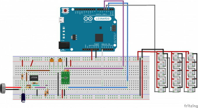
1. SchematicAs you can see from the schematic there are two macro-blocks: the audio block and the LEDs block.
The audio block is composed by an operational amplifier (LM358) used to amplify of a factor A = 1M/100k = 10, the signal provided from the microphone and the MSGEQ7. The MSGEQ7 samples the output signal of the amplifier and sends an analog value, proportional to the presence of each frequency in each band, to the Arduino's A0 input.
The LEDs are linked in series: the DOUT of the previous LED is attached to the DIN of the next. All the 5V and the GND are linked in parallel. The LEDs are driven by the Arduino's pin 3 using the Adafruit Neo Pixel Libary.
2. How it worksIn this example only two values of the seven provided by the MSEQ7 are used. In particular those corresponding to the bands 400Hz and 1 kHz. In base of the analogRead() of these two values, the LEDs will blink more or less brightly and more or less from blue to red (blue + red = purple)! The eye effect is very nice!
3. CodeFirst of all we need to read the analog values coming out from the MSGEQ7. This can be done using the function readMSGEQ7() which generates step signals and reads the corresponding analog value according to the datasheet of the component.
After this, we can simply use the values to modify the color of the LEDs using the function colorWipe!
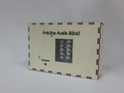
4. MountingYou can make this project on a breadboard or on a perfboard (as we did) and put it in a very cool box!
5. BoxWe decided to make a wood box for this project. It can be found in the attachments of the lesson. Laser-cut it!


_3u05Tpwasz.png?auto=compress%2Cformat&w=40&h=40&fit=fillmax&bg=fff&dpr=2)

Comments