ArduinoKoen
Published © GPL3+

Arduino very fast read and very cheap scope!

Arduino analog read at 77 kHz, no interrupts needed. Graphical representation of data on Serial Monitor.

IntermediateShowcase (no instructions)8,924
Arduino very fast read and very cheap scope!

Things used in this project

Story

Read more

Schematics

RC filter used for demo.

Shapes square wave of pin 8. Resulting signal is fed into pin A0.

Code

very_fast_analog_read

C/C++
reads analog data at 77 kHz or faster
/*  This small program shows that Arduino UNO is capable of recording analog readings at a rate of at least 77 kHz (maybe even 154 kHz).
 *  First, the analog digital converter setup registers (ADSCRA and ADSCRB) are set in such a way that analog values will be read and put in the ADCH register continuously at a rate of 77 kHz. 
 *  This ADCH register may then be read at any desired frequency. If the reading frequency is faster than 77kHz, the same value will be reported multiple times.
 *  Advantage of this approach is that no interrupt is needed (most sketches that I found so far wait for the analog read to get a new fresh result and will then read that value).
 *  
 *  Instead of 10-bit, only the 8 most significant bits are read. This reduces noise and allows for much more compact storage. An 8 bit number can be stored in a byte, a 10 bit number 
 *  will take an integer (2 bytes). At a sampling rate of 77 kHz, the memory of arduino will be full very rapidly.... 
 *  
 *  Timer2 is used to read the values at regular intervals. First the timer overflow flag is set to zero. Then actions are performed. 
 *  Then the controller waits for the overflow flag to be set. As long as the execution time of all actions fits in the period for the flag to be set, this will yield a very regular sampling.
 *  
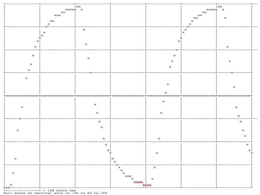
 *  The result is shown as a graph in the Serial Monitor. I guess a graphical display will allow for a much better view of the data (work to be done).
 *  
 *  Author: Koen Meesters
 *  Date:   16/09/2020
 *  
 *  Electrical scheme used for testing:
 *  
 *  
 *  Pin 8----[ 220 OHM ]----+----[ 220 OHM ]----+-----[ 220 OHM ]----+-------- Pin A0
 *                          |                   |                    |  
 *                          |                   |                    |
 *                         === 100 nF          ===  100 nF          === 100 nF    
 *                          |                   |                    |  
 *                          |                   |                    |
 *  GND --------------------+-------------------+--------------------+
 *  
 *  
 */

void setup() {
  Serial.begin(9600);
  delay(1000);
  Serial.println("start setup");
  delay(1000);

  /*  The bit of code below was taken from:
   *  http://yaab-arduino.blogspot.it/p/oscope.html
   */
  ADCSRA = 0;             // clear ADCSRA register
  ADCSRB = 0;             // clear ADCSRB register
  ADMUX |= (0 & 0x07);    // set A0 analog input pin
  ADMUX |= (1 << REFS0);  // set reference voltage
  ADMUX |= (1 << ADLAR);  // left align ADC value to 8 bits from ADCH register

  // sampling rate is [ADC clock] / [prescaler] / [conversion clock cycles]
  // for Arduino Uno ADC clock is 16 MHz and a conversion takes 13 clock cycles
  //ADCSRA |= (1 << ADPS2) | (1 << ADPS0);    // 32 prescaler for 38.5 KHz
  ADCSRA |= (1 << ADPS2);                     // 16 prescaler for 76.9 KHz
  //ADCSRA |= (1 << ADPS1) | (1 << ADPS0);    // 8 prescaler for 153.8 KHz

  ADCSRA |= (1 << ADATE); // enable auto trigger
//  ADCSRA |= (1 << ADIE);  // enable interrupts when measurement complete --> KM: disabled here, because no interrupts will be used
  ADCSRA |= (1 << ADEN);  // enable ADC
  ADCSRA |= (1 << ADSC);  // start ADC measurements

// set Timer2  to fast PWM, no prescaling, inverted pin 3
// in this sketch only the overflow flag of Timer2 will be used to trigger the reading frequency.
  TCCR2A = 0;
  TCCR2B = 0;
  TCCR2A = _BV(COM2A1) | _BV(COM2B1) | _BV(COM2B0) | _BV(WGM21) | _BV(WGM20); 
  TCCR2B = _BV(CS20);
  
  delay(1000);
  pinMode(8, OUTPUT);  //for testing a square wave signal will be produced on pin 8
  Serial.println("end setup");
  delay(1000);
}

const byte maxData = 255;   //this value could be chosen larger if desired
byte data[maxData];         //here the data will be stored
unsigned long int t0 = 0;   //(t1-t0)/255 should be equal to 1/77000*1000000 (otherwise the execution time of the actions is to large).
unsigned long int t1 = 0;

bool state = 0; //state of output at pin 8

void loop() {
  t0 = micros();
  
  TIFR2 = TIFR2 | _BV(TOV2); //reset overflow flag

  for (int i=0; i<maxData; i++) {
    data[i] = ADCH;        //read the analog value and store in memory
    PORTB = byte(state);   //this statement puts the square wave at pin 8 (pin 8 is the least significant bit of PORTB)
    if((i&B00000111) == 0) {state = !state;} /* prescaler to set frequency of square wave at pin 8: 
                                              * B00111111 = 64 B00011111=32 B00001111=16 B00000111=8, frequency will be: Timer2Freq/(prescaler*2)  
                                              */
    
    /* More statements could be put here. Perhaps data could be written to SD card, but I did not test if writing of one character to SD card 
     * can be performed in the little time available here
     */
    
    while((TIFR2 & _BV(TOV2)) == 0) {
      ; //wait for timer overflow flag
    }
    TIFR2 = TIFR2 | _BV(TOV2);  //reset overflow flag
  }
  
  t1 = micros();

  Serial.println(t0);
  Serial.println(t1);
  Serial.println(t1-t0);
    
  for (int i=0; i<maxData; i++) {
    Serial.println(data[i]);
  }

  makeGraph(maxData);
  delay(2000);
}

//make a Graph on the Serial monitor
void makeGraph(byte numData) {
  
  const byte horLineInt =  8;
  const byte verLineInt = 16;
  const byte y_offset   = 32;

  const byte screenHeight =  64;
  const byte screenWidth  = 128;
  if(numData<screenWidth) {numData = screenWidth;}  //only data that fit on the screen will be shown

    
  for (byte y=0; y<=screenHeight; y++) { //each line, starting at bottom of the graph
    for (byte t=0; t<numData; t++) {     //each character, starting from left to right
      char character = ' ';    //put a space 
      if (t%verLineInt == 0) {
        character = '|';       //put a vertical line for the grid on regular intervals
      }
      if ((screenHeight-y-y_offset)%horLineInt == 0) {
        character = '-';     //put a horizontal line for the grid on regular intervals
        if (y == y_offset) {
          character = 'o';     //put a horizontal line with zeros in the grid
        }
        if (t%verLineInt == 0) {
          character = '+';      //put a '+' where horizontal and vertical grid lines meet
        }
      }
      if (round(data[t]/4.0) == screenHeight-y) {
        character = 'x';        //if data point supposed to be here, then put an 'x'    
      }
      Serial.print(character);  //put the character on the Serial Monitor
    }
    Serial.println();           //next line
  }
  Serial.println("+---------------+ = 128 micro sec");  //add horizontal scale dimenstion
  //              01234567890123456
  Serial.println("Full scale on vertical axis is -5V to 0V to +5V"); //add vertical scale data
}


Credits

ArduinoKoen

ArduinoKoen

0 projects • 6 followers

Comments