

Hardware components | ||||||
 |
| × | 2 | |||
_ztBMuBhMHo.jpg?auto=compress%2Cformat&w=48&h=48&fit=fill&bg=ffffff) |
| × | 1 | |||
| × | 1 | ||||
| × | 1 | ||||
| × | 1 | ||||
| × | 1 | ||||
| × | 1 | ||||
| × | 1 | ||||
| × | 1 | ||||
 |
| × | 1 | |||
 |
| × | 1 | |||
 |
| × | 1 | |||
| × | 1 | ||||
| × | 1 | ||||
| × | 1 | ||||
| × | 1 | ||||
 |
| × | 1 | |||
 |
| × | 1 | |||
 |
| × | 1 | |||
| × | 4 | ||||
| × | 1 | ||||
Software apps and online services | ||||||
 |
| |||||
Hand tools and fabrication machines | ||||||
 |
| |||||
The signals from field sensors can be affected by noise generated by power surges, lightning strikes or other EMI (Electromagnetic Interference) sources and also by ground potential differences. One method to avoid most of these problems is to use a complete isolation from the field.
The isolation of an input sensor will require a separate power supply to power the field device and the circuit that realize the insulation itself.
More details can be found in the post published in my blog: http: //ardupiclab.blogspot.it/.
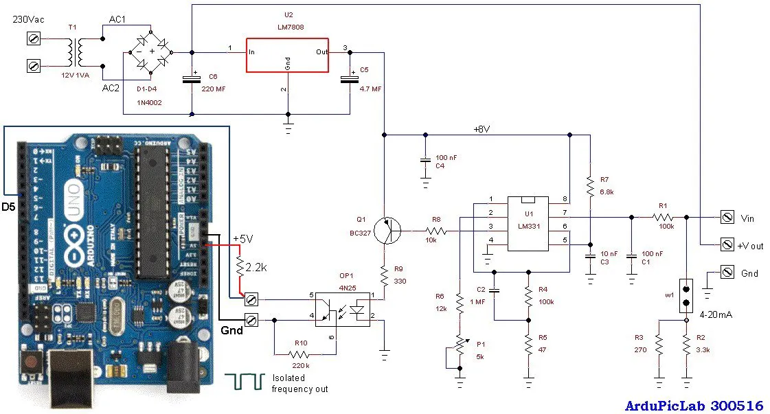
Schematic of the circuit
The circuit accepts an input voltage from about 20mV to 5V or a current of 4 to 20 mA (with the jumper W1 inserted). The two resistors in parallel R2 and R3 give a value of about 250 ohms, in order to have 1V to 5V for 4mA to 20mA current input.
Just three wires and a resistor are required to connect the circuit to the Arduino Uno. The output of the opto-coupler should be connected to the digital input D5 with a pull-up 2.2k resistor connected to the +5V of Arduino.
If an input range of 10V is required, a 15V power supply is necessary, so you have to change the 7808 regulator with a 7815. The transformer T1 also has to power supply the sensor, so it must have an adequate voltage and power. The trimmer P1 must be adjusted to obtain a conversion factor of about 1kHz/V.


Comments