

To test the circuit, I wrote a simple program that sends to the DAC0 of Arduino Due, values of N according to the table: {0,512,1024,2048,3072,3584,4095}. They are generated in succession, each time I press the a button connected to pin 32. In the picture below you can see the circuit connected to my system, based on an Arduino Due and a LCD display.
For the calibration measurements I used both a digital DMM, as shown in the photo, and a more accurate high resolution voltmeter on a precision 200.0 Ohm resistor, acting as load.
The results of these measurements were very good, as is also clear from the trend curve shown in the following figure and from R2, almost equal to one.
Circuit scheme
Arduino Due does not have an analog output voltage from 0 V to Vref, but from 1/6 to 5/6 of the reference voltage, corresponding to voltage values of 0.55 V and 2.75V with a typical Vref = 3.3 V. This is also confirmed by the Atmel (see bibliography 1).
I do not know if it is wanted by the ARM Cortex-M3 CPU designers, but the ratio between the maximum value and the minimum of the output voltages of Arduino Due is exactly five, such as that between 20 and 4 mA, the standard used for the transmission of analog measurements in the industrial plants.
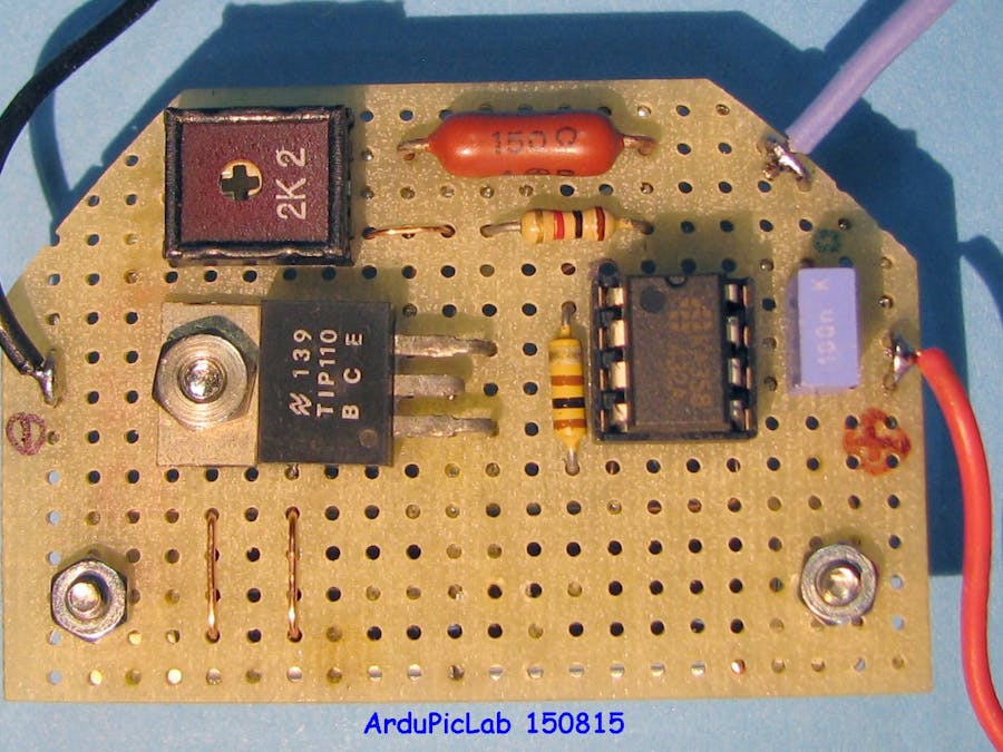
This has facilitated the design of an electronic circuit in order to obtain at the output a current range of 4 to 20 mA. The following diagram shows this simple circuit. It uses a single-rail LM358 operational amplifier and an NPN darlington transistor and a few other components.
The operational amplifier U1 and the transistor Q1 realize a tracking system, so that the voltage on emitter resistor R2 is equal to the input voltage. Keeping constant the voltage on a resistor, by the Ohm's law, means that even the current is constant. In this way, the transistor emitter current Ie, flowing in R2, is dependent on the input voltage, therefore the circuit behaves as a current generator controlled by the input voltage.
From Kirchhoff's Current Law the collector current is: Ic = Ie – Ib, where Ib is the base current of transistor: Ib = Ic /hfe and hfe is the common-emitter current gain. Using a transistor with a hfe> 100 or greater, we can neglect the base current of the transistor and assert that also the collector current remains constant and proportional to the input voltage. A darlington transistor has an even greater current gain, so that we can assume that Ic = Ie.
The trimmer pot is used to adjust the maximum output current (20 mA) at the maximum number (4095) of the DAC or the maximum output voltage. This value, in the typical case of 3.3*5/6 is equal to 2.75 V, for which:
R2 = 2.75V /20mA = 137.5 Ω
In practice there may be slightly different values, therefore, it's better to use a potentiometer to precisely calibrate the current.
Powering the circuit with 5 V, supplied by of Arduino, the load can’t have higher voltages of 1 volt. Indeed, at 20 mA the voltage on R2 will be equal to about 2.75 V, which must be added to the Vce of the transistor which must not saturate. During the tests I used a digital ammeter that require a maximum of 0.2V on its terminals. For these reasons it is better to use higher supply voltages as 12 V or, better, 24 V. By varying the supply voltage does not involve variations of the circuit, but only an increase of dissipation on the transistor. In these cases a darlington medium power transistor is a good choice, as a TIP110, BD675, or similar.
Don’t use operational amplifier as LM741, LM1458, TL081 and other that are not suitable for single-supply.
I do not know if it is wanted by the ARM Cortex-M3 CPU designers, but the ratio between the maximum value and the minimum of the output voltages of Arduino Due is exactly five, such as that between 20 and 4 mA, the standard used for the transmission of analog measurements in the industrial plants.
This has facilitated the design of an electronic circuit in order to obtain at the output a current range of 4 to 20 mA. The following diagram shows this simple circuit. It uses a single-rail LM358 operational amplifier and an NPN darlington transistor and a few other components.
The operational amplifier U1 and the transistor Q1 realize a tracking system, so that the voltage on emitter resistor R2 is equal to the input voltage. Keeping constant the voltage on a resistor, by the Ohm's law, means that even the current is constant. In this way, the transistor emitter current Ie, flowing in R2, is dependent on the input voltage, therefore the circuit behaves as a current generator controlled by the input voltage.
From Kirchhoff's Current Law the collector current is: Ic = Ie – Ib, where Ib is the base current of transistor: Ib = Ic /hfe and hfe is the common-emitter current gain. Using a transistor with a hfe> 100 or greater, we can neglect the base current of the transistor and assert that also the collector current remains constant and proportional to the input voltage. A darlington transistor has an even greater current gain, so that we can assume that Ic = Ie.
The trimmer pot is used to adjust the maximum output current (20 mA) at the maximum number (4095) of the DAC or the maximum output voltage. This value, in the typical case of 3.3*5/6 is equal to 2.75 V, for which:
R2 = 2.75V /20mA = 137.5 Ω
In practice there may be slightly different values, therefore, it's better to use a potentiometer to precisely calibrate the current.
Powering the circuit with 5 V, supplied by of Arduino, the load can’t have higher voltages of 1 volt. Indeed, at 20 mA the voltage on R2 will be equal to about 2.75 V, which must be added to the Vce of the transistor which must not saturate. During the tests I used a digital ammeter that require a maximum of 0.2V on its terminals. For these reasons it is better to use higher supply voltages as 12 V or, better, 24 V. By varying the supply voltage does not involve variations of the circuit, but only an increase of dissipation on the transistor. In these cases a darlington medium power transistor is a good choice, as a TIP110, BD675, or similar.
Don’t use operational amplifier as LM741, LM1458, TL081 and other that are not suitable for single-supply.

Comments