

Hardware components | ||||||
 |
| × | 1 | |||
 |
| × | 1 | |||
 |
| × | 4 | |||
 |
| × | 1 | |||
 |
| × | 1 | |||
Software apps and online services | ||||||
 |
| |||||
I built this simple project using XinaBox ☒CHIPS. The SW01 was used to measure the ambient temperature. If the temperature was between 12°C and 18°C, an email would be sent to indicate the cold weather. If the temperature is between 18°C and 25°C, moderate temperature conditions would be emailed and if the temperature is above 25°C, the email would read hot conditions.
Step 1: Software Setup
Download the following libraries and add them to the Arduino IDE Libraries. Also download the board and follow the instructions that accompany it.
- xSW01 library
- xCore library
- ESP8266 Board
After installing the board, select the "Generic ESP8266 Module" as shown below and replicate other parameters under Tools. Be sure to select the correct COM port.
Step 2: Gmail and BASE64 setup
This project can only be accomplished using Gmail. Set up your gmail account by following this link ESP8266 GMail Sender. Since you are allowing less secure apps, it is advisable to create another Gmail account and not use your personal account. Now, using BASE64, copy and paste your email address into the textbox and press encode. Save the encoded character string somewhere on your computer. Do the same for your password. See the example below.
Step 3: Build for programming
Connect your IP01 and CW01 using the XC10 bus connectors as shown below.
Insert the combination into an available USB port. Download the code or preferably copy and paste each code in different tabs into one Arduino IDE Window and follow the instructions below.
Step 4: Inputting your details
In the 'Temp_Email' tab, scroll to the 'email_details' function and replace "your email" with the email you chose to use. See image below.
In the 'Gsender.h' tab, copy and paste your username and password that you encrypted on BASE64 in their respective locations as well as the email address you are sending from. See the image below.
In the 'Temp_Email' tab, insert your WiFi details. Refer to below image.
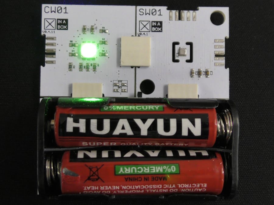
Now compile and upload the code to your CW01 board. Once uploaded the RGB LED on the CW01 should be green before you remove it.
OperationRemove IP01 from your computer and separate the two CHIPS. IP01 is no longer needed. Now click SW01 and CW01 together using the XC10 bus connectors as shown below.
Now connect the power supply (PB04) as shown below.
Flip the switch of the PB04 to the on position and an email will be sent to you based on the temperature. If you're looking for something more permanent, consider the PU01 connected to a fixed USB power supply and keep your project somewhere safe on your porch. This way you'll never forget your jacket at home.


Comments