

Hardware components | ||||||
 |
| × | 1 | |||
 |
| × | 1 | |||
 |
| × | 1 | |||
 |
| × | 1 | |||
 |
| × | 1 | |||
 |
| × | 1 | |||
| × | 1 | ||||
Software apps and online services | ||||||
 |
| |||||
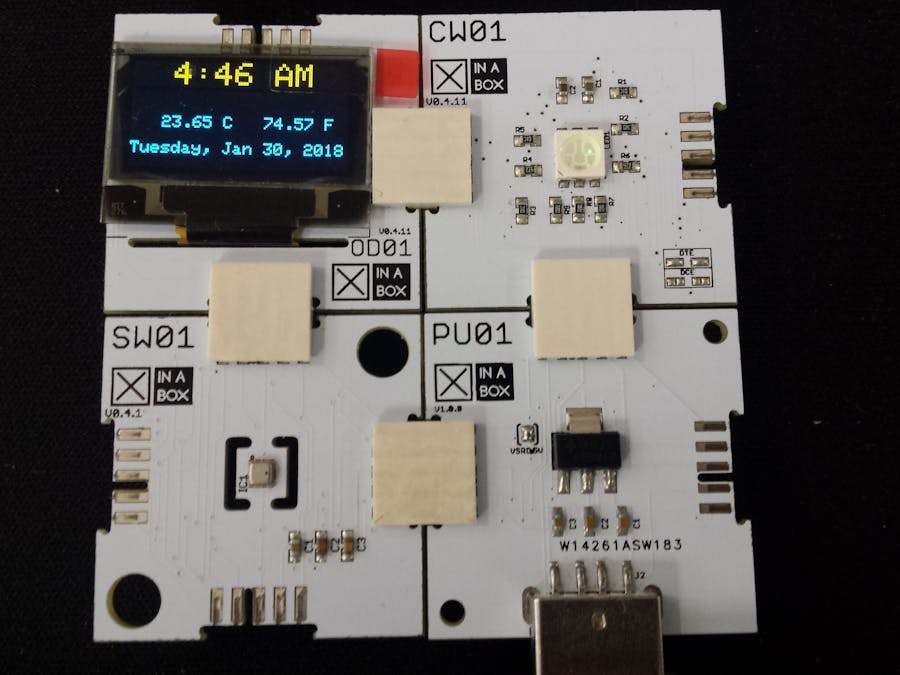
I built this project to display the date, UCT time and temperature using XinaBox ☒CHIPS that uses the I2C bus protocol. The time was retrieved from a google NTP server. The ambient temperature was measured using the SW01 ☒CHIP and was displayed on the OD01 ☒CHIP OLED display in Celsius and Fahrenheit. The image below shows the OLED display.
You will require the following libraries and software for this project.
- Arduino IDE - Development Software in which you will code
- xSW01 - Temperature sensor library
- xCore - Core library for XinaBox ☒CHIPS
- xOD01 - OLED Display library.
- Timezone - Library to choose your timezone
- Time - To use time functions
- NTPClient - Enables you to get time from a server
- You will also need to download the ESP8266 board and follow the instructions that accompany it in order to have the board installed
Once downloaded you will install the IDE and the libraries. It is fairly straight forward if you follow the instructions.
Step 2: AssembleYour main ☒CHIP that will execute and process the program is the CW01. It is based on the ESP8266 WiFi Module and uses the I2C bus protocol. In order to program to the CW01, you will need a programming ☒CHIP. The IP01 allows us to program the CW01 via the USB port on our computer simply by clicking together the two ☒CHIPS using XC10 bus connectors and inserting it into the the USB port. No wiring and no soldering required. One thing to take note of is the orientation of the ☒CHIP identification names. They should all be orientated in the same direction. You should now have the following setup.
If you are familiar with ☒CHIPS you may connect every ☒CHIP together using XC10 bus connectors that you want to use for your project and then insert it into the USB port. We will be using SW01 temperature sensor and the OD01 OLED display.
Download or copy and paste the code below into your Arduino IDE. If you aren't making any changes to the code simply enter your WiFi details in their respective fields as shown below. Also enter a reliable NTP time server. I've used a Google time server for this project.
Now compile and upload. Make sure you've selected the correct COM port and board under the tools menu in the Arduino IDE. Once uploaded, the time, date and temperature should show as below.
You may now remove the unit from your USB port and separate each ☒CHIP by simply pulling it apart. Since the programming is complete, IP01 is no longer required. You may now connect your project in any manner you wish as long as the identification names are all orientated in the same direction. To power our unit we will use the PU01. This allows us to power it from a normal power bank or any 5V USB power supply. I've connected mine as shown below.
Simply connect a power bank or similar to PU01 and your ☒CHIP project is complete.
This project will take 20min to complete. If you want the time in your location, consider looking at the example code in the Timezone library or do some arithmetic with the UTC time. No wires were used and no soldering was required.


Comments