Originally, I wanted to have a remote weather station independent of Wifi or internet applications to see the current weather conditions outside our home. Radio communication for a local area network appeared to be the best option. Additionally, many of the projects I encountered involved using one remote Arduino and Xbee radios to communicate with a computer. My desire was to remove the computer dependency and only use Arduinos for both the transmitter and receiver.
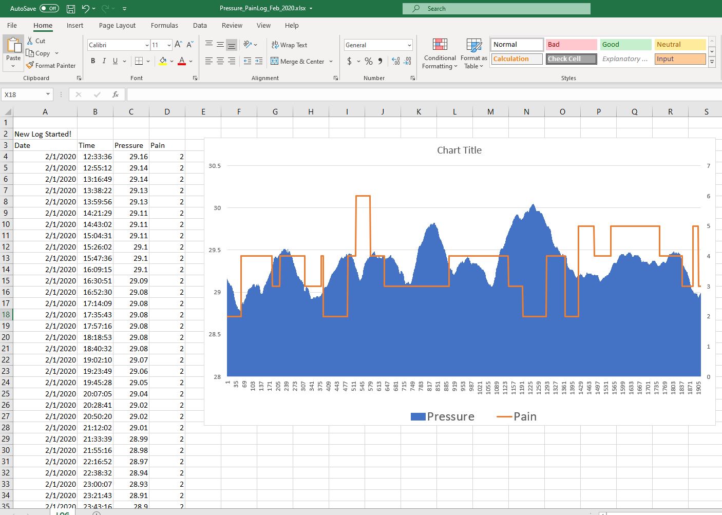
Amid working through the project, my wife requested the additional capability to record her nerve pain levels to see if there is any correlation with changing barometric pressure. To address this, data logging and an additional potentiometer were added to record pressure data and to input her pain levels. There are still a few undedicated analog pins on the receiver that perhaps could be used for other inputs if desired. Instead of correlating pressure to personal pain level inputs, one could compare other personal sensory changes with changes in humidity or temperature values.
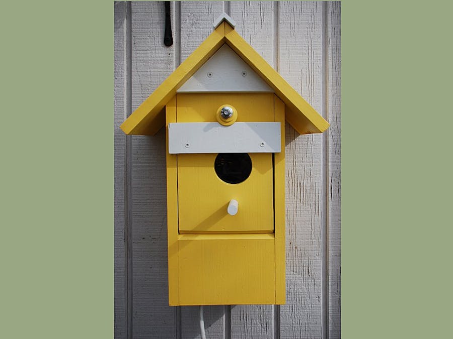
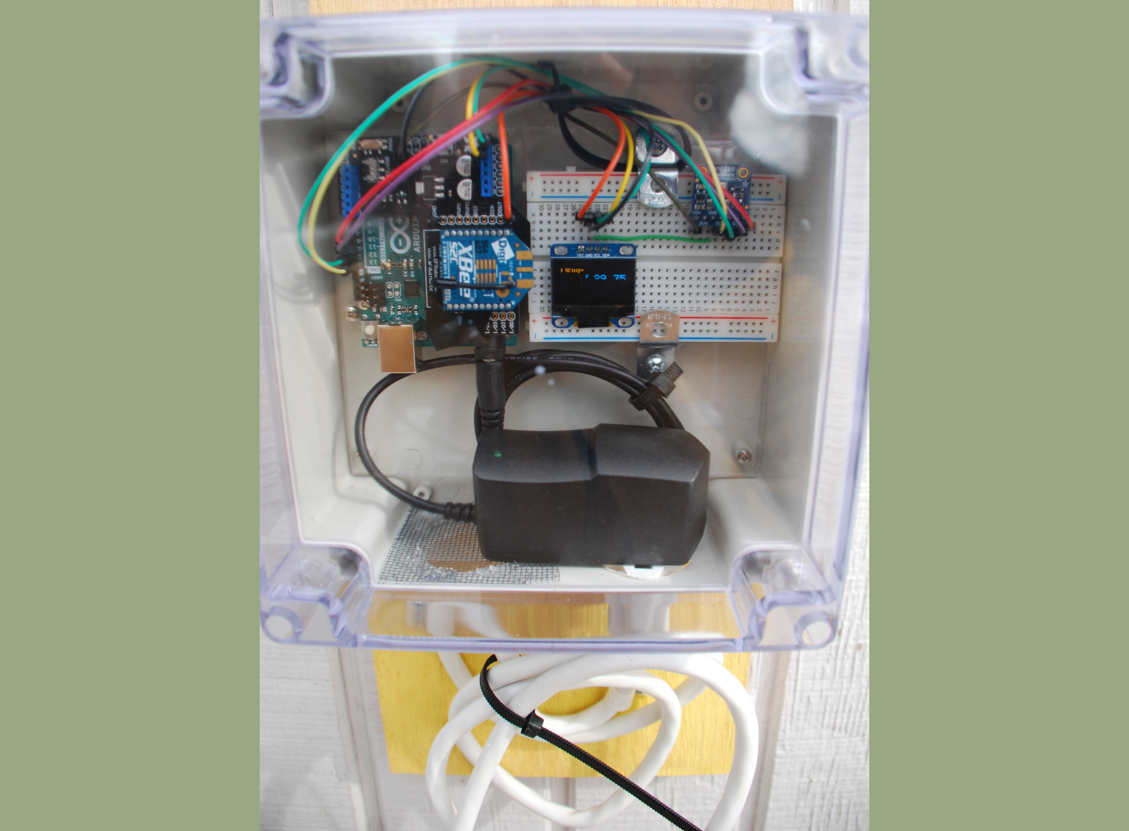
The receiver is complete in a black plastic box under a kitchen cabinet. The transmitter is housed in a weather proof box on the exterior of our potting shed. The box is inserted within a faux bird house to make the unit blend in with the garden space.
Receiver installed under kitchen cabinet
Transmitter in potting shed
Eventually I would like to use this transmitter - receiver combination for sculptures that respond to changing environmental conditions in other or adjacent location. This nice utilitarian project is a good test to learn how the remote sensors and receivers behave. I have already noticed the Xbee radios respond erratically if wireless devices like tablets are waved too close to them. So this is one condition I will have to keep in mind when placing the transmitter - receiver in public spaces.
Instructions:
Step 1: Download the XTCU application for programming the XBee radios.
Download all required Arduino libraries to the libraries folder:
OLED libraries - Wire.h; SPI.h; Adafruit_GFX.h; AdafruitSSD1306.h
BME280 libraries - Adafruit_Sensor.h; Adafruit_BME280.h
RTC libraries – RTClib.h;
Data Logging – SD.h
LCD – LiquidCrystal.h
Step 2: Review the XBee Comunication JAB NotesFromBlum chapter 11.pdf below and follow through the instructions to program the XBee radios with the XBee Explorer.
Step 3: DF Robot XBee Shield:
For this entire project keep the XBEE/USB switch on the XBEE side. The RUN/PROG switch will alternate, if you are uploading a sketch to the Uno move the switch to PROG. After uploading, switch back to Run to enable the Xbee Radio. If you forget to switch to PROG during a sketch upload, the sketch will just timeout.
Testing the Xbee Radios:
After configuring the radios in XCTU. Wire up a potentiometer to a Uno with an XBee Shied and Radio. The center lead of the pot connects to A0 pin and the outer leads to ground and 5V.
On the XBee Shield move the switch to PROG. Upload the Test Sketch by Jeremy Blum at the bottom of this page. Now move the jumper switch on the XBee Shield to RUN. Leave the Sketch open in the IDE, but remove the Uno from your computer and power with external power source. Reconnect the XBee Explorer with the other Xbee radio to your computer USB. In the IDE select the XBee USB port for the COM port in the Tools menu. Then open the serial window and if the radios are communicating the potentiometer values should appear in the serial window. After confirmation, disconnect power from both the Uno and XBee Explorer and switch the radios. Re-power units and check the XBee Explorer COM port in the IDE Tools menu and open serial window to check communication again.
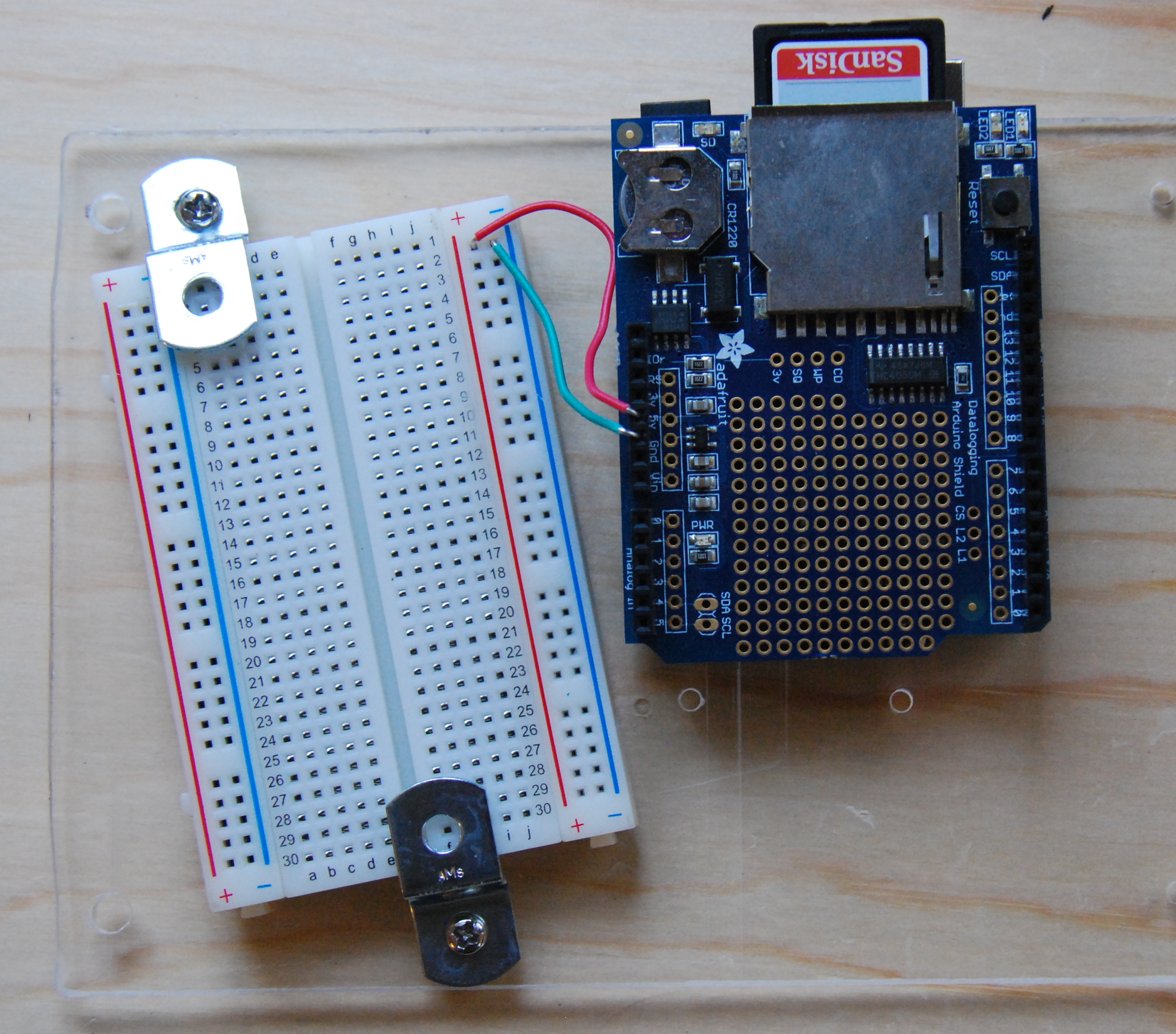
Step 4: Review the Adafruit Data Logging Shield tutorial at the bottom of this page. Follow it through the formatting of the SD card and setting the Real Time Clock. If you want to go further with the tutorial to check how the logger is working, feel free to do so. NOTE: this tutorial is for an older model data logger, Newer loggers use a different RTC from the one used in the attached tutorial. You must download the newest tutorial from Adafruit and the associated libraries in order to set the time on the newer RTC identified as a PCF8532.
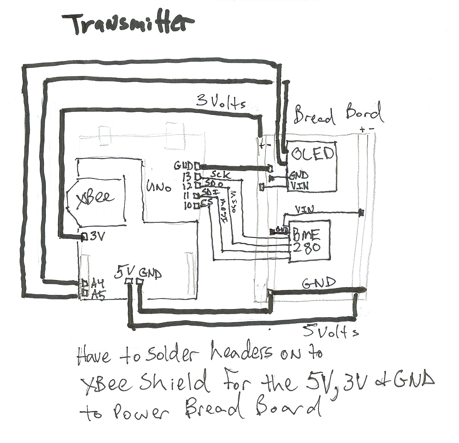
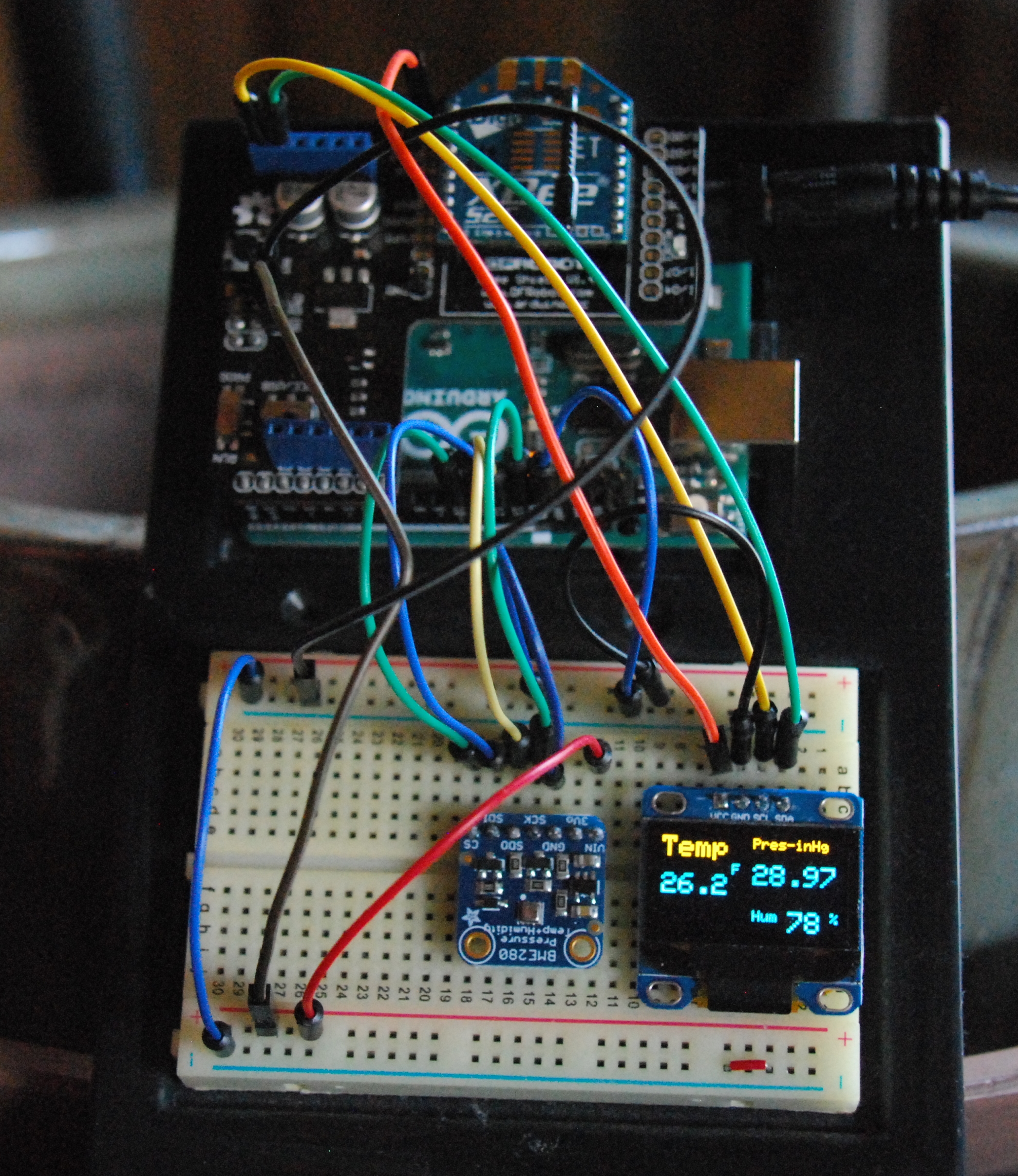
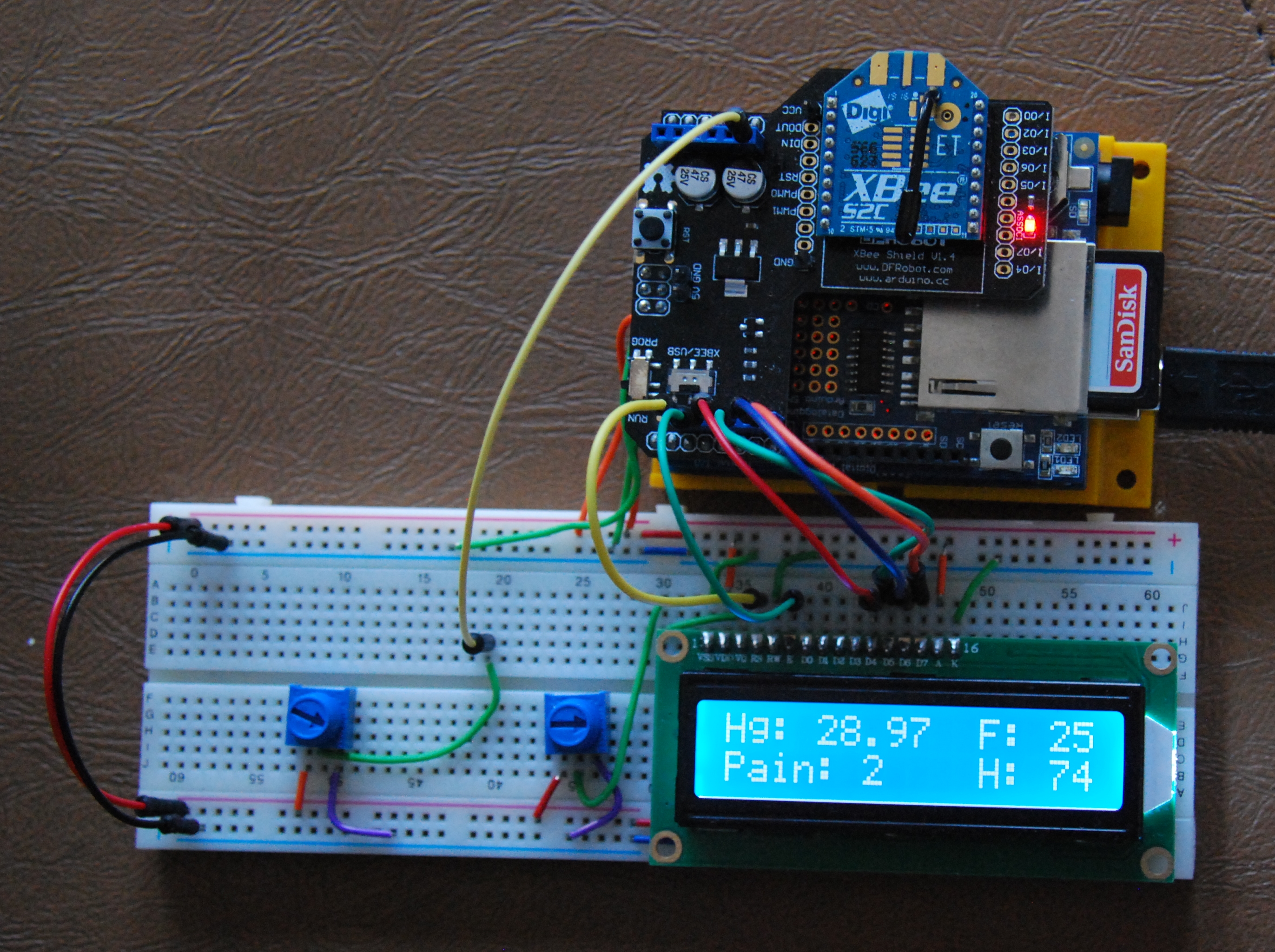
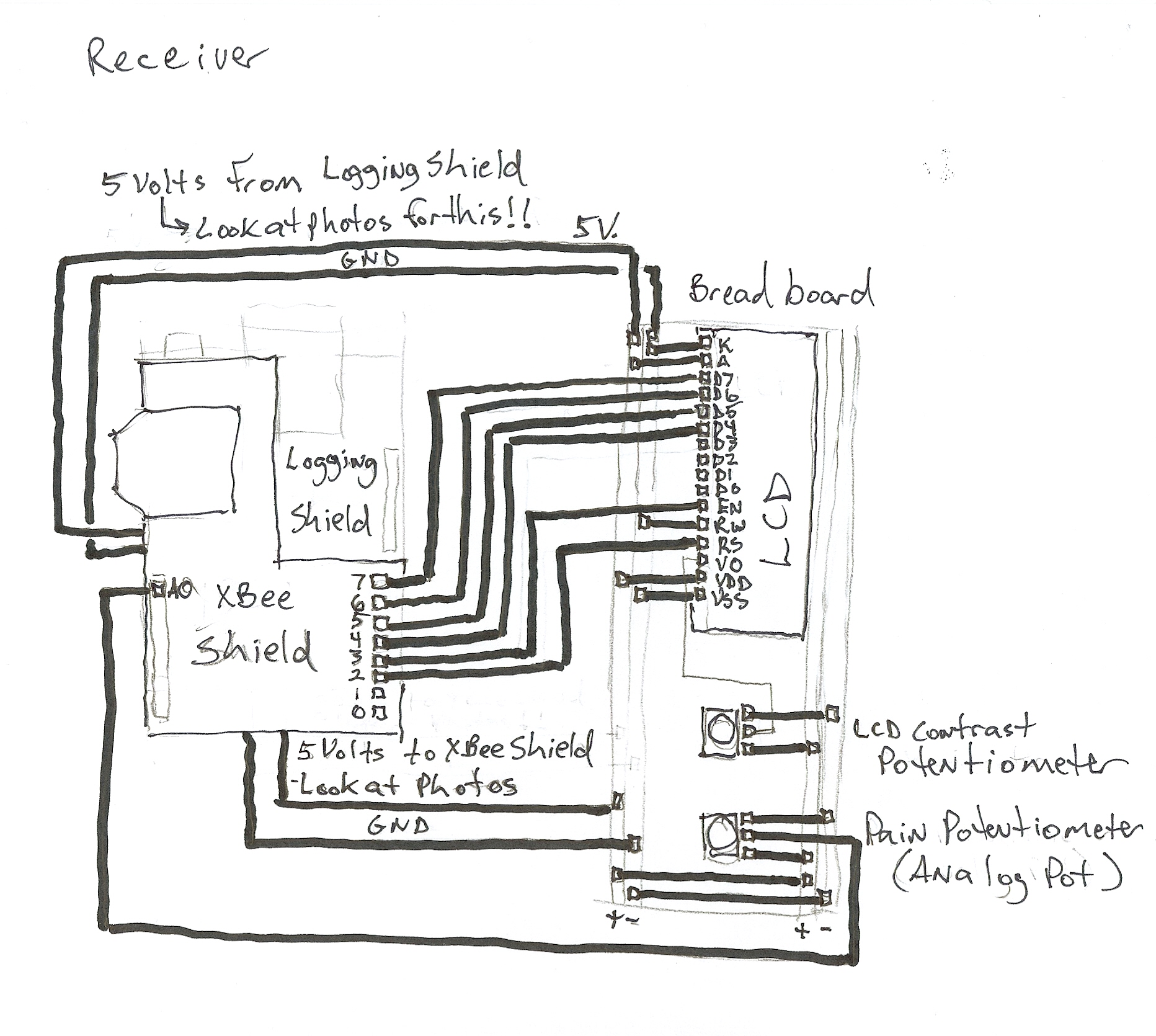
Step 5: Wire up the Transmitter and Receiver as illustrated in the photos bellow and wire diagrams.
Step 6: Upload the sketches to the Transmitter and Receiver. Remember to switch the jumper on the XBee Shields from RUN to PROG when uploading. Return to RUN after uploading.


_ztBMuBhMHo.jpg?auto=compress%2Cformat&w=48&h=48&fit=fill&bg=ffffff)


_nf92bPIM1D.JPG)
_lk64rZMpLZ.JPG)


_YszCM74MKs.JPG)

_5oO5kuJ0CA.JPG)
_NrTiqo4eVA.JPG)
_r9gPBRcwZi.jpg)
_hUI5NuWPSR.JPG)
_QZIQCvmKIe.JPG)
_ROvCrR3JsJ.JPG)


_3u05Tpwasz.png?auto=compress%2Cformat&w=40&h=40&fit=fillmax&bg=fff&dpr=2)


_nf92bPIM1D.JPG)
_lk64rZMpLZ.JPG)
_YszCM74MKs.JPG)
_5oO5kuJ0CA.JPG)
_NrTiqo4eVA.JPG)
_r9gPBRcwZi.jpg)
_hUI5NuWPSR.JPG)
_QZIQCvmKIe.JPG)
_ROvCrR3JsJ.JPG)
Comments