

Hardware components | ||||||
_ztBMuBhMHo.jpg?auto=compress%2Cformat&w=48&h=48&fit=fill&bg=ffffff) |
| × | 1 | |||
 |
| × | 1 | |||
 |
| × | 1 | |||
| × | 1 | ||||
| × | 1 | ||||
 |
| × | 1 | |||
| × | 1 | ||||
| × | 1 | ||||
 |
| × | 1 | |||
 |
| × | 1 | |||
Software apps and online services | ||||||
| ||||||
| ||||||
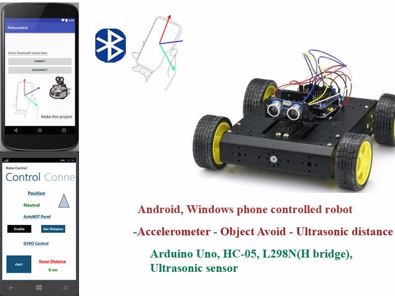
Hello there guys, My Initial Idea was to make a robot through scratch parts (the robotic Structure mainly) and making it controlled by a Windows phone 8 Application through Bluetooth, The Robot is controlled by the Accelerometer sensor of the Phone but however the development of the application is not covered here in this tutorial instead I have provided link to store. The project covers the Accelerometer controlling and also the autonomous part but you guys can seperate them if you're not willing to integrate anyone of them.
The application is also compatible with other bluetooth projects and can be configured in the settings of the application (detailed explanation in the last).
App links:
Windows phone : https://www.microsoft.com/store/apps/9NBLGGH5J3WS
Android : https://github.com/Anas-siddiqui/Robocontrol
Ok Let's start making the project
- Accelerometer Mode
Starting from the Arduino we will first connect the DC motors and the bluetooth module. Connect the HC-05 pins accordingly as shown in the Schematic diagram, As per logic the RXD pin of bluetooth module goes into the TXD of arduino Digital pin 11 ( Which we have assigned in our code) and TXD of the module into the RXD of arduino digital pin 10. The Vcc of the module is connected to arduino 5V pin, both the module and arduino are powered seperately in order to avoid any connection issues due to the current. Ground pin of module is connected to gnd of arduino (any of them, all are common). On powering the bluetooth module blinks its LED continuously.
Motor driver L289N is powered by another battery which I recommend must be powerful enough to drive the motors, Please keep in mind that the more load is applied on the motor the more it will drop the current from the battery. Connect the pins as described in the diagram, The IN1-IN4 pins are used to control the directions by making them HIGH and LOW from the code so the order described in the diagram is important otherwise the motors will work in opposite direction.
Please note that there is a 5V regulator pin in the driver which generates 5V when the driver is poweredup, You can utilize this pin to power your other components which require 5V to powerup, We will Utilize this pin later when we will attach servo and other components to it.
The First Part is done here and you can now connect the application
- First pair the device in the Phone's setting- Bluetooth The passcode I dont remember correctly maybe 1234 or 12345
- After pairing, the device will be Shown in the Application and then tap on it to connect
- On connecting the application will show connected and LED of the Module will blink in intervals which will indicate that it is now connected
- On the Control page press the Start button to start using the Accelerometer Mode, The video might help you guys more
Object Avoid Mode
For this mode we will just program the arduino a little bit more , We will connect an Ultrasonic and Servo motor.
Ultrasonic Sensor
The Vcc pin of ultrasonic is connected to to 5V regulator pin of driver , ground of the sensor to any ground of the circuit and Trig,echo pins as described in diagram. Because I was facing some error in distance reading that's why I connected this sensor to the driver's 5V pin otherwise if your arduino battery is good enough then you can connect it to the 5V pin of arduino too and the ground remains the same(any of the grounds).
That's it all the components are connected and we are now ready to go for the mode 2
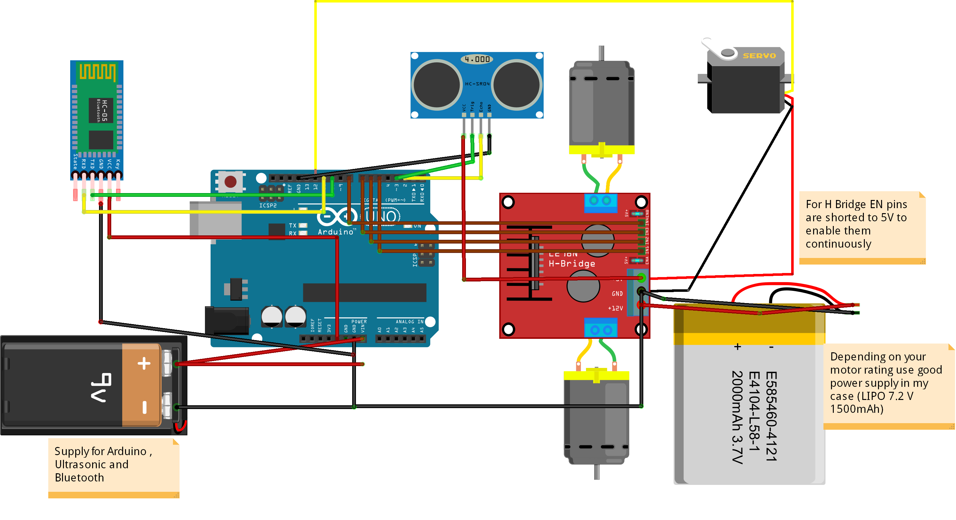
Schematic Diagram

Schematic Diagram
Starting from the Arduino I'm using a 9V battery to power the arduino+bluetooth. The +ve terminal of the battery is attached to the Vin pin of arduino and -ve terminal to ground(any of them doesn't matter) of the arduino.
- HC-05 Bluetooth module for which the Vcc of the module is connected to 5V regulator pin of arduino, ground of the module to gnd of arduino, the RXD pin of bluetooth module to Digital pin 11 of arduino and TXD of module to Digital pin 10 of arduino.
-Motor driver L298N which we are powering through another battery , The +ve terminal goes into the +V of the driver and -ve of the battery goes into the gnd of the driver . The driver regulates the voltage and give output of 5V in the 5Vout pin , The IN1-IN4 pins are used for controlling and are connected to arduino digital pins as described in the diagram and finally the motors are connected to Motor A and Motor B pins.
-UltraSonic Sensor , The Vcc is connected to the 5V regulator pin of Motor driver L298N, Ground pin of the sensor to any ground (All the grounds are common so it doesnt matter) , Trig of the sensor to arduino Digital pin 2 and Echo of the sensor to arduino Digital pin 3.
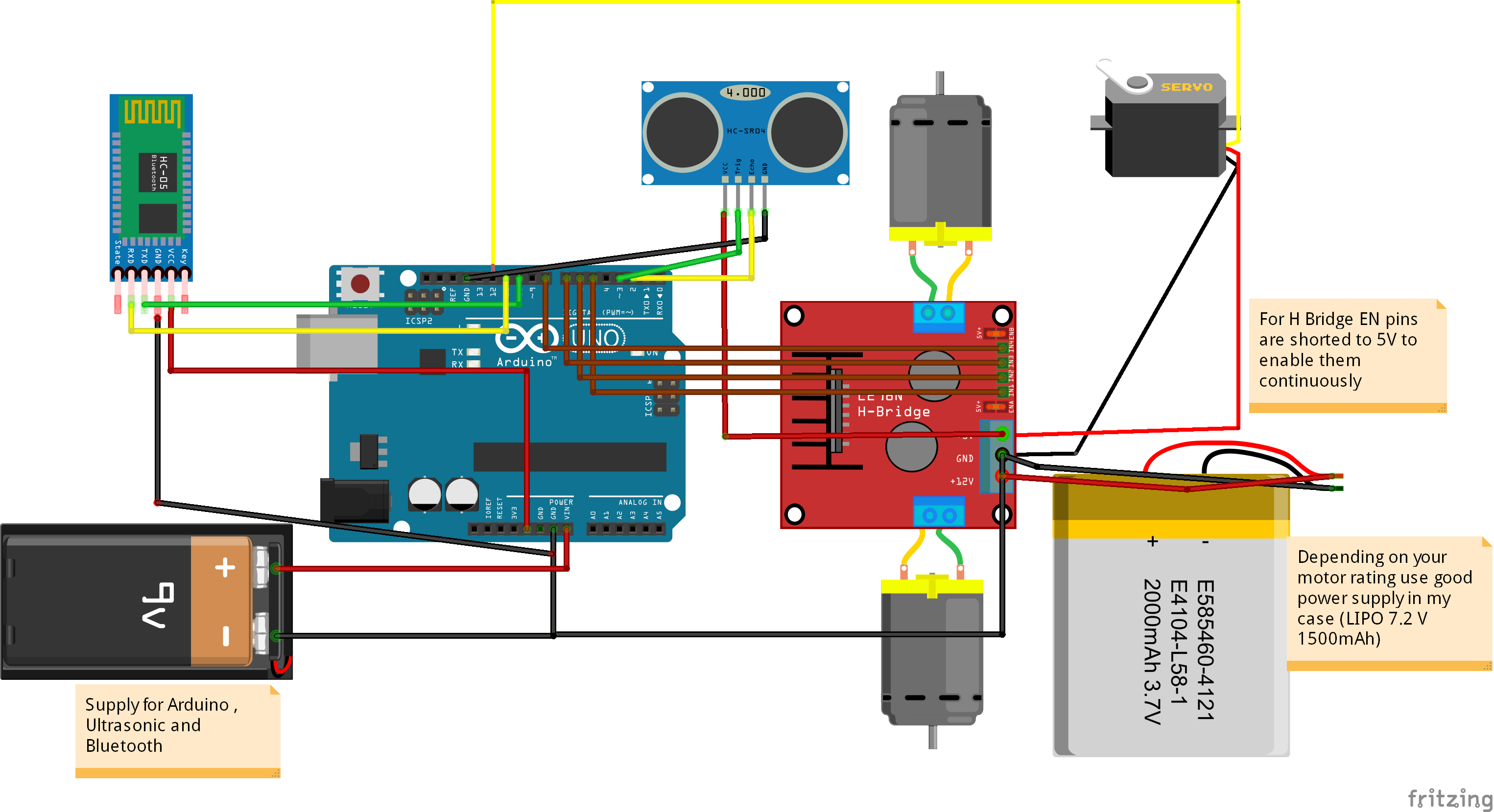
Schematic Diagram
Starting from the 9 V battery
-The positive terminal goes into the Vin of arduino
-The negative of battery goes into the ground
For the Bluetooth Module
- RXD goes into the digital pin 11
- TXD goes into the digital pin 10
- Vcc goes into the arduino 5V pin(to get the 5V for power)
- gnd goes to any of the grounds
For Motor Driver L298N
- The IN pins are for controlling and goes into digital pins of arduino(there order matter otherwise motor will work in opposite direction)
- +V of driver goes to the positive terminal of the other battery
- Ground is connected to negavtive of battery
- Motors are connected in Motor terminals A & B
For the Ultrasonic Sensor
- Vcc goes to the 5V pin of motor driver (to get 5V supply to power sensor)
- ground can be any of them
- Trig and echo pins as accordingly shown in the diagram
Other Notes
More details can be found in the story section and make sure to check all the grounds are connected to each other .


_3u05Tpwasz.png?auto=compress%2Cformat&w=40&h=40&fit=fillmax&bg=fff&dpr=2)
Comments