// Code example for LED Matrix obtained from MD_PAROLA examples
// Libraries
#include <MD_Parola.h>
#include <MD_MAX72xx.h>
#include <SPI.h>
#include <WiFi.h>
#include <NTPClient.h>
#include <WiFiUdp.h>
// Font Data
#include "Font_Data.h"
// WIFI Login
const char *ssid = "Your SSID";
const char *password = "Your Password";
// Time Client Creation
WiFiUDP ntpUDP;
NTPClient timeClient(ntpUDP);
String formattedTime;
// Starting brightness of the display from 0-15
int brightness = 0;
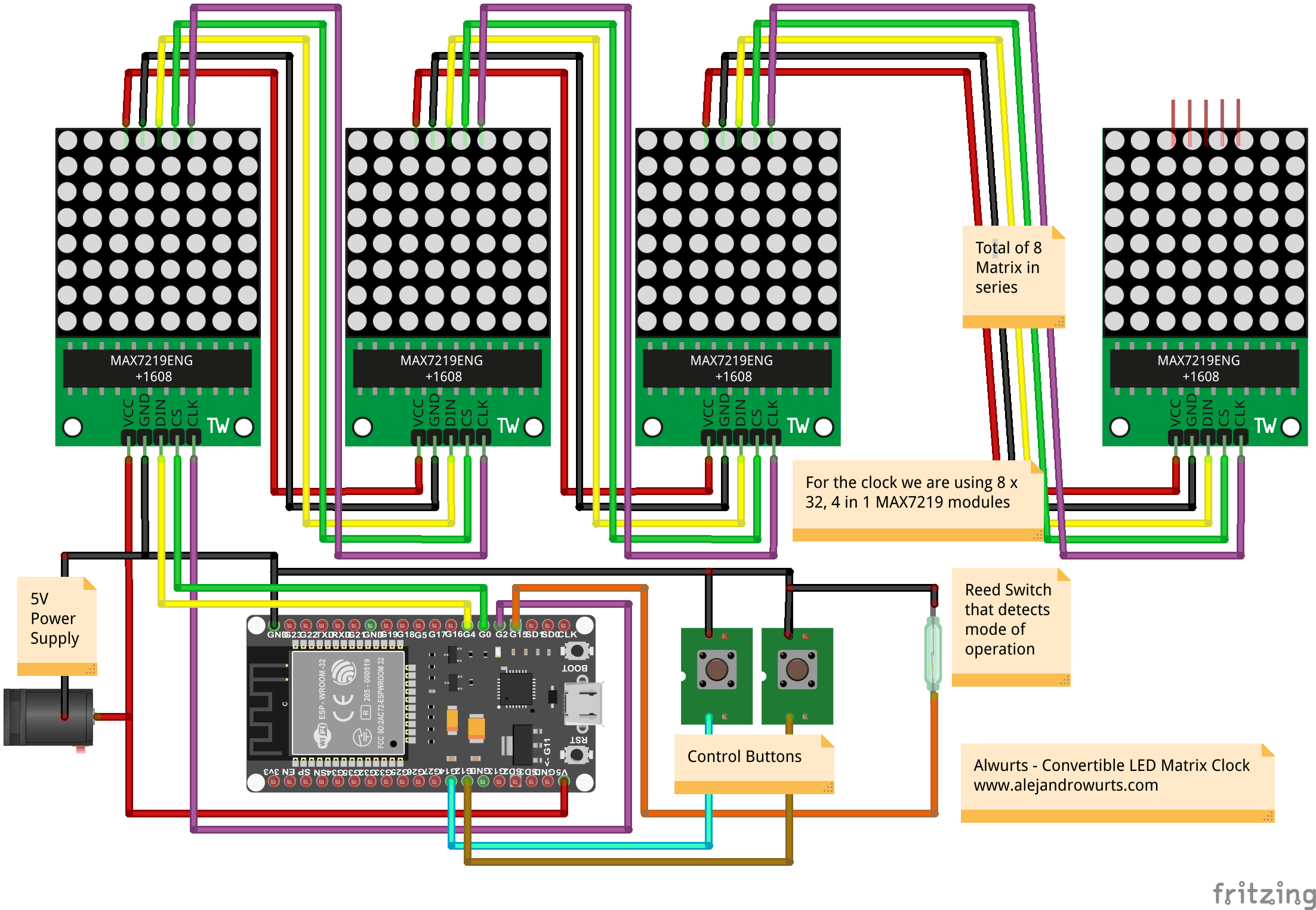
// Led Matrix Setup for 2 (4 in 1 led modules)
#define HARDWARE_TYPE MD_MAX72XX::FC16_HW
#define MAX_ZONES 2 // 2 Zones for 2 displays
#define ZONE_SIZE 4 // Size of each module
#define MAX_DEVICES (MAX_ZONES * ZONE_SIZE)
// Definition of zones
#define ZONE_UPPER 1
#define ZONE_LOWER 0
// Software SPI Connections
#define CLK_PIN 2
#define DATA_PIN 4
#define CS_PIN 0
// SPI Connection to md_parola library setup
MD_Parola P = MD_Parola(HARDWARE_TYPE, DATA_PIN, CLK_PIN, CS_PIN, MAX_DEVICES);
#define SPEED_TIME 75
#define PAUSE_TIME 0
#define MAX_MESG 50
// Hardware adaptation parameters for scrolling
bool invertUpperZone = true;
// Global variables
char szTimeL[MAX_MESG]; // mm:ss\0
char szTimeH[MAX_MESG];
void getTime(char *psz, bool f = true)
// Code for obtaining time and formating it
{
timeClient.update();
formattedTime = timeClient.getFormattedTime();
int h, m;
h = formattedTime.substring(0, 2).toInt();
m = formattedTime.substring(3,5).toInt();
// Use 12 hour clock, comment for 24 hour clock
if (h > 12){
h = h - 12;
}
Serial.print(h);
Serial.print(":");
Serial.println(m);
sprintf(psz, "%02d%c%02d", h, (f ? ':' : ' '), m);
}
void createHString(char *pH, char *pL)
{
// Function to create the top part of the double heigh display
for (; *pL != '\0'; pL++)
*pH++ = *pL | 0x80; // offset character
*pH = '\0'; // terminate the string
}
void setup(void)
{
Serial.begin(115200);
// Initialise the LED display
P.begin(MAX_ZONES);
P.setInvert(false); // Invert color of letters from red to black
P.setIntensity(brightness); // Set the initial brightness
// Set up zones for 2 halves of the display
P.setZone(ZONE_LOWER, 0, ZONE_SIZE - 1);
P.setZone(ZONE_UPPER, ZONE_SIZE, MAX_DEVICES - 1);
P.setFont(DoubleHeightNumbers);
//P.setCharSpacing(P.getCharSpacing() * 2); // double height --> double spacing
//P.setCharSpacing(0);
// Set the effects for the clock according to double height clock
P.setZoneEffect(ZONE_UPPER, true, PA_FLIP_UD);
P.setZoneEffect(ZONE_UPPER, true, PA_FLIP_LR);
P.displayZoneText(ZONE_LOWER, szTimeL, PA_RIGHT, SPEED_TIME, PAUSE_TIME, PA_PRINT, PA_NO_EFFECT);
P.displayZoneText(ZONE_UPPER, szTimeH, PA_LEFT, SPEED_TIME, PAUSE_TIME, PA_PRINT, PA_NO_EFFECT);
// Wifi connection
Serial.print("Connecting to ");
Serial.println(ssid);
WiFi.begin(ssid, password);
while (WiFi.status() != WL_CONNECTED) {
delay(500);
Serial.print(".");
}
// Print local IP address and start web server
Serial.println("");
Serial.println("WiFi connected.");
Serial.println("IP address: ");
Serial.println(WiFi.localIP());
timeClient.begin();
// Set offset time in seconds to adjust for your timezone, for example:
// GMT +1 = 3600
// GMT +8 = 28800
// GMT -1 = -3600
// GMT 0 = 0
timeClient.setTimeOffset(-18000);
// Input declarations with pull ups
pinMode(15, INPUT_PULLUP); // Reed
pinMode(16, INPUT_PULLUP); // Button 1
pinMode(17, INPUT_PULLUP); // Button 2
}
void loop(void)
{
static uint32_t lastTime = 0; // millis() memory
static bool flasher = false; // seconds passing flasher
// If statements to increase or deacrease the brightness
if(digitalRead(16) == 0 && brightness < 15){
brightness++;
P.setIntensity(brightness);
Serial.print("Brightness: ");
Serial.println(brightness);
delay(250);
}
if(digitalRead(17) == 0 && brightness > 0){
brightness--;
P.setIntensity(brightness);
Serial.print("Brightness: ");
Serial.println(brightness);
delay(250);
}
P.displayAnimate();
// If animation terminated
if (P.getZoneStatus(ZONE_LOWER) && P.getZoneStatus(ZONE_UPPER))
{
// If a second passed
if (millis() - lastTime >= 1000)
{
lastTime = millis();
getTime(szTimeL, flasher);
// If true we are in double height mode, else single row
if(digitalRead(15)==1){
// Double height settings
P.setFont(DoubleHeightNumbers);
createHString(szTimeH, szTimeL);
P.setZoneEffect(ZONE_UPPER, true, PA_FLIP_UD);
P.setZoneEffect(ZONE_UPPER, true, PA_FLIP_LR);
P.displayZoneText(ZONE_LOWER, szTimeL, PA_RIGHT, SPEED_TIME, PAUSE_TIME, PA_PRINT, PA_NO_EFFECT);
P.displayZoneText(ZONE_UPPER, szTimeH, PA_LEFT, SPEED_TIME, PAUSE_TIME, PA_PRINT, PA_NO_EFFECT);
} else {
// Single height setting
P.setFont(singleRow);
P.setZoneEffect(ZONE_UPPER, false, PA_FLIP_UD);
P.setZoneEffect(ZONE_UPPER, false, PA_FLIP_LR);
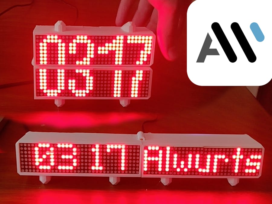
P.displayZoneText(ZONE_LOWER, "Alwurts", PA_CENTER, 0, 0, PA_PRINT, PA_NO_EFFECT);
P.displayZoneText(ZONE_UPPER, szTimeL, PA_CENTER, 0, 0, PA_PRINT, PA_NO_EFFECT);
}
//createHString(szTimeH, szTimeL);
// Flasher comes frome example code
//flasher = !flasher;
P.displayReset();
// synchronise the start
P.synchZoneStart();
}
}
}


Comments