
Hardware components | ||||||
| × | 1 | ||||
 |
| × | 1 | |||
| × | 1 | ||||
| × | 1 | ||||
| × | 1 | ||||
| × | 1 | ||||
 |
| × | 1 | |||
 |
| × | 1 | |||
| × | 1 | ||||
| × | 1 | ||||
| × | 1 | ||||
| × | 1 | ||||
| × | 1 | ||||
| × | 1 | ||||
Software apps and online services | ||||||
| ||||||
Hand tools and fabrication machines | ||||||
 |
| |||||
Hello Everyone! This project is made for all the people who have trouble waking up in the morning!
IntroductionI used to wake up every morning tired, groggy, and not the same person who had aspirations for a productive, healthy life and sleep schedule. I spent countless mornings finding loopholes to alarms I set for myself in the morning, just so that I could get back to bed, ANYTHING to feel the sweet embrace of my sleepy chambers. I frequently found myself staying in bed until the last minute, rushing to get ready for school, and as a result, not be able to achieve any of the tasks I set out for myself in the morning, making for a sluggish morning and mind in the process. I kept telling myself that I was going to fix this issue through sheer willpower, and EVERY. SINGLE. TIME., I failed. As someone with ADHD, it already takes an obscene amount of energy to get important tasks that I don't necessarily like done. Add sleep inertia to that mixture, and we weren't going anywhere. And so I moved to incorporating extraneous motivations and systems to forcibly wake myself up. My most successful system was that of a picture alarm system, where an app I downloaded on my phone set off an alarm at the time I wanted to wake up. This alarm would sound until I scanned a barcode on a deodorant bottle in my bathroom, which in the aftermath I would be "woken up" enough to get out of bed. This worked for me for a little bit, until I got used to the routine. Remember, me in the morning would do almost ANYTHING to get back to bed; no matter the energy cost. After a while, I began to scan the deodorant bottle, and then walk back to bed, continuing a deleterious cycle of continuous snoozes and hitting the snooze button and losing trust in my ability to take control of my life.
RealizationI realized that the only thing that cold stop myself, an unstoppable force, was an immovable object, and what better immovable object than a door!
ConceptionPart of fighting with your own internal machinery, your BRAIN, is finding ways to trick yourself. I won't lie, It was extremely difficult trying to create something new that could stop my spell of unadulterated slumber, so I decided to focus on things that had already worked for me in the past. I decided to keep the barcode-alarm app idea, but also add other measures to the plan.
ConceptThe concept that culminated with this line of thought is as follows: I used the alarm-barcode system as bait to get myself into the bathroom, then I would use some sort of mechanism that would detect my motion and close + hold the door of my bathroom shut, so I wouldn't be able to leave for a couple of seconds without extreme effort. Since ADHD responds to cues, this lack of being able to complete my goal of going back to sleep could snap the real "me" to reality enough to wake up and start my day on time.
V1This iteration was a failure, but not for the reasons one would think. The basic idea was to use an RTC and PIR sensor to detect my movement within the hours I wake up, propagating a cammed servo arm to push my bathroom door closed within a couple seconds. I CADded this design for HOURS on end, eventually coming up with a design that would allow for free rotation of the servo arm around the hinge axis, but allow for extra vertical support around the expanse of the arm to reduce its potential to sag or break off from its wall mount. A swivel caster wheel is used at the support arm tip to allow for the free rotation of the arm path, while allowing for adaptation to rotational angle mismatches. The issue with this mechanism is that my bathroom door is a "pull" to close and not a "push" to close, an easily preventable oversight that led to a whole lot of wasted time. I ultimately had to abandon this version of the system, but the public Onshape document is attached if anyone is interested in modifying it to their own interests/uses (warning it's a bit messy, but the actual mechanistic assembly is easily found by clicking through the tabs on the bottom).
To be completely honest, this setback was both a curse and a blessing in disguise. It allowed me to more directly use sensors and electronic devices that I had learned about in class, and allowed for easier conceptualization as well.
Below are some drawings I thought of for the pulley mechanism
The steps to creating my final iteration of this project are listed below:
Step 1: Create a mount for the servo. ***I originally designed this mount out of wood to accommodate heavy pressures on both sides of the servo, both a 2 kg weight on one side pulling the servo down, and another side attached to the doorknob, with the servo acting as a mediating capstan. I needed to mount the servo to 2 studs in my wall to prevent anything from ripping out due to these extreme forces, but the mechanism ended up causing more harm than good due to lack of friction on the servo's included aluminum spool. I eventually made the switch to using the spool as a winch, attached to just the doorknob, ergo why the mount looks excessively clunky. By all means, if you find a way to woodwork the servo into fitting perfectly into the wood, and find a way to minimize the prominence of the wood on the wall, please do so.*** To create a "balance" between the wood, gravity, and servo, I cut out a hole in the wood to just over fit the rectangular shape of the servo, then attached two separated pieces of wood with the same thickness to the edges of the initial wood board to create a static- seesaw for the servo to fit in. This way, the servo becomes too large to back out of the mount. The front side is reinforced with a piece of wood that is jammed into the extra space between the servo and hole in order to stabilize the structure.
Step 2: Tie a string (preferably high tensile metal wire or nylon, but twine will do in a pinch) to the aluminum winch using the provided holes.
Step 3: Place the aluminum spool on the servo, then open the door to its fullest extent, and measure out and tie the twine to the doorknob to a length that allows for free rotation of the door + passage through the door around the hinges when the aluminum spool is fully unfurled.
Step 4: Attach the limit switch to the door frame such that its internal button is clicked when the door is fully shut.
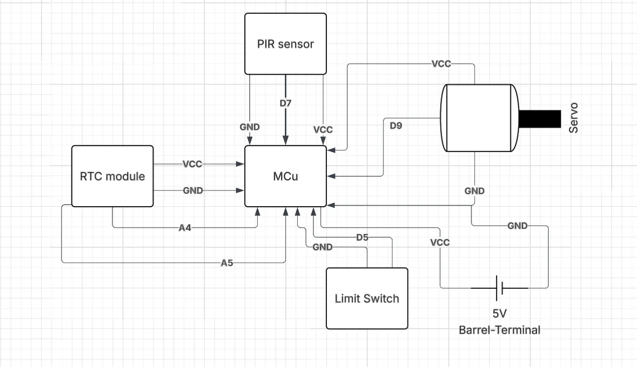
Step 5: ***assume all other power pins, GND & Vin/5V/PWR are connected to their respective ports//Dupont wire extenders may be needed for sufficient length to attach peripherals to Arduino. Any 24-22 gauge wire(s) should work.***MAKE SURE ALL GROUNDS ARE CONNECTED***
Connect SDA and SCL of the RTC to pins A4 and A5 (respectively) of the Arduino Nano. Connect the data wire of the PIR to pin 7 on the Arduino. Connect the limit switch's data wire to pin 5 of the Arduino. Attach the data pin of the servo to pin 9 of the servo. Attach the positive end of the barrel adapter terminal to 5v and attach the negative terminal to ground. For my current setup, I used a mini breadboard as a baseplate for the Arduino pins, and a breadboard to unify all the sensors/peripherals.
Step 6: Mounting, Code Uploading, and Wire Management
I designed and printed out cases for the PIR sensor and the Mini + Regular Breadboard, RTC, and Arduino complex. The 3d models are attached below. As for wire management, I used electrical tape to wrap up any extra extension cord lengths and connections, and double sided tape along the door frame edges to neaten everything up. Proper wire organization is sacrosanct in this project to mitigate the risk of wires/parts from being pulled inadvertently due to the motion of the motor and twine. Various makeshift notches were cut post-printing in the main mount apparatus for easy access to the Arduino's USB input and the barrel input of the power adapter. These will be modified in the attached models, however. The PIR sensor wire was fed through a gap in the top of the door and into the bathroom. In order to protect the electrical integrity of the sensor during possible bouts of humidity/steam in the bathroom, I decided to use silicone sealant around all open areas of the PIR apparatus. Note: In order to use the PIR mount properly, the Fresnel Lens has to be placed in the apparatus first and have the outer edge of its convex side be masked with silicone sealant. All visual installation videos are outlined in the following link: https://imgur.com/a/wmPvcHn
After mounting is completed, all that needs to be done is to plug in the AC power cord into an outlet and upload the code.
Step 7: Enjoy! **I am not responsible for any personal issues or late starts to the day that arise from this project. Operate at your own risk please!**


Comments