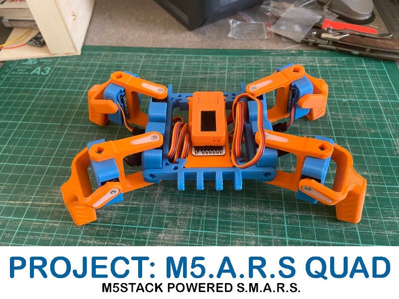
In this guide I will show you how to build a S.M.A.R.S QUAD which uses M5Stack 180 Servo's, M5StickC controller and 8Servo Hat electronics.
Step 1 - Print the Parts.Go to https://www.thingiverse.com/thing:2755973 and download the S.M.A.R.S QUAD parts.
Print out 4 for the servo covers, 4 of the servo cover M's, 2 feet and 2 feet M's.
Next gotohttps://github.com/Ajb2k3/M5ars_quad/tree/main/3Dand download 8servomountv3.stl and print out.
Check your printers tolerances as the fit of the mount was very tight to the frame when I printed the parts.
Step 2 - Modify the Servo'sModifying the servos to use in the S.M.A.R.S QUAD is not as scary as it sounds. The modification is not damaging, non permanent, and does not break the warranty.
The servos come fitted with a mounting cage which allows it to be fitted to the frame found it the kit. To use the on the S.M.A.R.S QUAD we need to remove this frame. To remove the frame I just gently pushed the clips that hold the servo on so that the servo just pops out without breaking the clips.
The M5Stack servos come with short leads and extensions. Place all the servos into the 8 mounts but don't press the cables in.Take 4 extension leads and connect them to 2 of the servos in the servo case and two to the servo M case, these will be the leg/knee servos.
Step 4 - Assemble the 3D Printed parts.
Place the 8Servomount into the frame.
Place two of the servomounts and two of the servomount M's so that the horn mounts are close to the corners of the frame.
Next take the four servo arms and clip them over the servo cases but don't fit the servo horns yet.
The 8servo module should just fit into the support frame but the frame may need some filing if it doesn't. The switch points to the rear so that the RGB LED on the underside side in the hole of the support frame.
Next the four "Hip" servo connect to the four outer servo ports marked CH1, CH4, CH5 and, CH8. This is because the short leads mean that they wont reach any other port.
Next connect the four knee servo's making sure that the wire from each go to one of the corresponding available ports i.e.
- Front Left Hip = CH5,
- Front Left Knee = CH6,
- Front Right Hip = CH1,
- Front Right Knee = CH2,
- Rear Left Hip = CH8,
- Rear Left Knee = CH7,
- Rear Right Hip = CH4,
- Rear Right Knee = CH3,
Now that the M5.A.R.S QUAD is complete, the next step is testing calibration and programming.
For good information and guides for non M5Stack based S.M.A.R.S projects you can check out https://www.smarsfan.com by Kevin McAleer.


_t9PF3orMPd.png?auto=compress%2Cformat&w=40&h=40&fit=fillmax&bg=fff&dpr=2)


Comments