

This guide is sponsored by M5Stack and so makes use of their Official images.
Get Started with the M5Stack ACSSRIn this guide I will show you how to get started using the M5Stack ACSSR.
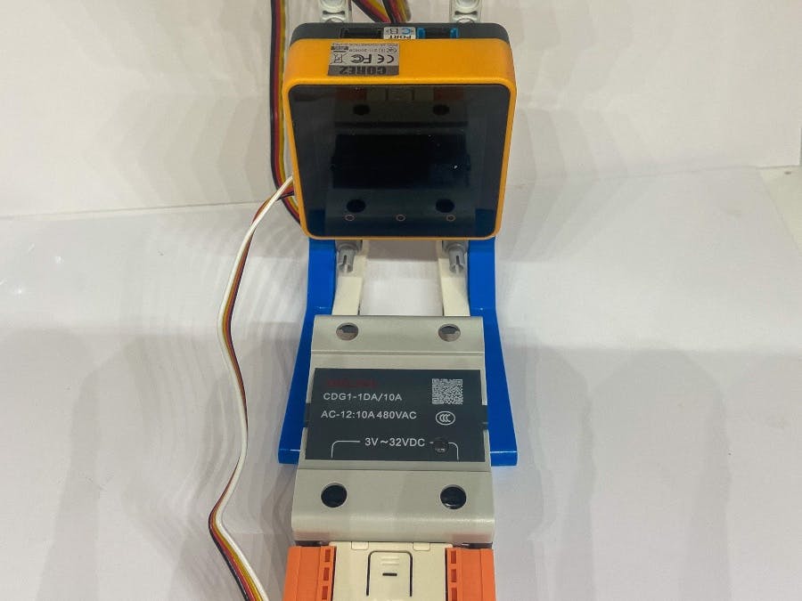
The ACSSR is made up of two modules, the first module being the actual ACSSR and the second being the ESP32 powered controller shown here in the official M5Stack Web documents as attached.
Out of the box, the ACSSR's ESP32 controller is programmed to operate in one of three modes selectable on startup.
- Button mode - The ACSSR is operated by the button on the front.
- I2C Mode - The ACSSR is operated by a controller connected to the I2C port.
- RS485 Mode - The ACSSR is controlled over an RS485/Modbus network.
To change the operating mode you must start with the ACSSR power off, Hold the button on the front and then connecting power. After two seconds the led will flash rapidly to show that it is mode select. Press the button on the front and to cycle through the modes and then press, hold for two seconds until the led blinks slowly and then release to set the mode. The three modes are identified by the colour of the LED. Red is for I2C mode, green is for button mode and yellow is for RS485/Modbus mode.
The mode is stored on memory even when powered off and to change or reset the mode back to the default I2C you need to repeat the power cycle.
In order to control the ACSSR in I2C and RS485/Modbus mode I am using the Core2 AWS as it is still set up on my desk from the Temperature monitor project.
Button Mode.When button mode is set you will see the button glow green. Pressing the button will illuminate the SSR's red led and turn on the SSR. Pressing the button will extinguish the red LED and deactivate the SSR.
I2C Mode.I would just like to make a shout out to M5Stack Forum member Felmue for helping me understand the Instructions as I was suffering from an "I haz Dumz" moment.
The ACSSR is connected to Port A of the Core2 AWS, the Core2 AWS is powered on and that is all that needs to be done Hardware wise.
Now load UIFLOW
If you go into the Units list to search for the ACSSR you won't find one. That doesn't mean that the ACSSR is unusable, it means we have to try another method.
For this go into Hardware>I2C Master menu to find the Blocks needed to access and communicate over I2C.
We first need to initialise the I2C bus on Port A with the Init Master Block.
Next we scan the I2C bus and use a Label Show block to display devices found on the bus. The Scan I2C device block is known as a value block and is used to retrieve data from a device. As a value block it needs a function block to operate and so here I use a Label Show function to display the data retrieved from the I2C bus scan.
Running an I2C bus scan can be a bit confusing at first because the scan returns a value of 80 in Decimal but I2C address are always printed in Hexadecimal. In order to find the Hexadecimal address we need to use a Decimal to hex converter. For this I use the Rapid Tables Decimal to Hexadecimal converter found here: https://www.rapidtables.com/convert/number/decimal-to-hex.html
If we type 80 into the converter and hit the convert button we get a return value of 0050. we only need the last two digits here so we remove the 00 and replace it with 0x giving us the address we are looking for of 0x50. If we look at the card that came with the ACSSR:
We can see that 0x50 corresponds with the I2C address shown under I2C Mode.
Next we need to tell the code to use the device with the address of 0x50 as a slave device. This is done with the Set Slave Addr block.
Adding the 1 second wait before setting the slave address give the I2C bus scan time to finish.
To control the ACSSR coil we need to seen one byte. this is done using the Send byte block.
Sending 0x01 turns the coil on while sending 0x00 turns the coil off.
The coil is not the only thing we can control, there is an RGB LED in the controller part that can be controlled using the registers 0x10 to 0x12. The colours are in hexadecimal but must be split into three values as shown below
In the following example I change the LED between red, green, and blue.
When M5Stack devices are used in RS485 mode they don't have units. To control them you have to select the RS485 unit or the ISO485 unit and plug them into the Core2 AWS.
The ACSSR then connects to the RS485 or IOS485 units with for wires connected to the screw terminals.
Unfortunately at the time of writing 31-July-2022, I have not been able to get RS485 Modbus to work and so will leave this as an incomplete Work In Process project.


Comments