

Hardware components | ||||||
| × | 1 | ||||
| × | 1 | ||||
| × | 1 | ||||
 |
| × | 1 | |||
 |
| × | 1 | |||
| × | 1 | ||||
| × | 1 | ||||
| × | 1 | ||||
Software apps and online services | ||||||
| ||||||
Hand tools and fabrication machines | ||||||
 |
| |||||
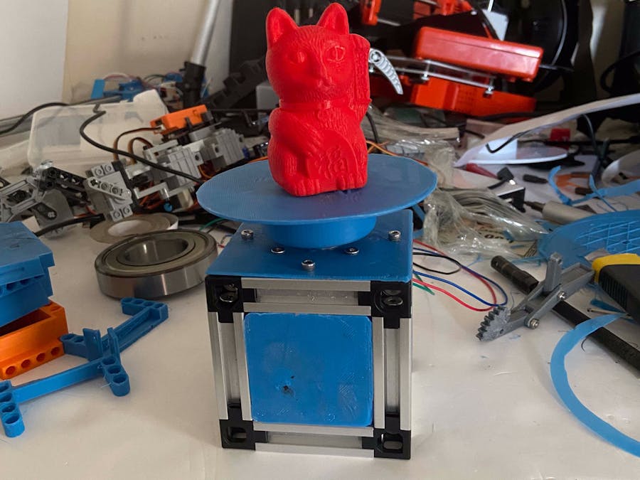
This turntable is a miniature version of my previous turntable project designed to use the smallest M5Stack products available.
The controller for this one is the new Atom Stepper motor kit from M5Stack https://m5stack.com/collections/m5-atom/products/atom-stepmotor-kit?ref=pfpqkvphmgr
I chose this as it only contains one stepper motor driver and is the simplest hardware controller that currently exist in the M5Stack Product line resulting in a much more compact design.
Step 1Take 4X 50mm lengths of 1515 extrusions and 4X corner pieces and join using the M4x8mm screws included with the corners.
Add 4X 50mm 1515 on to the base and secure using 4 more provided screws
Insert the slide nuts into the uprights as shown.
Connect 4 more corners with 4 more aluminium extrusions but insert slidenuts into the top of the extrusions before screwing together and attaching to the rest of the structure.
Goto https://www.thingiverse.com/thing:4567420, download the files and print out the top plate, front plate and table. The top plate is secured to the slide nuts using M3x6mm screws.
Step6.
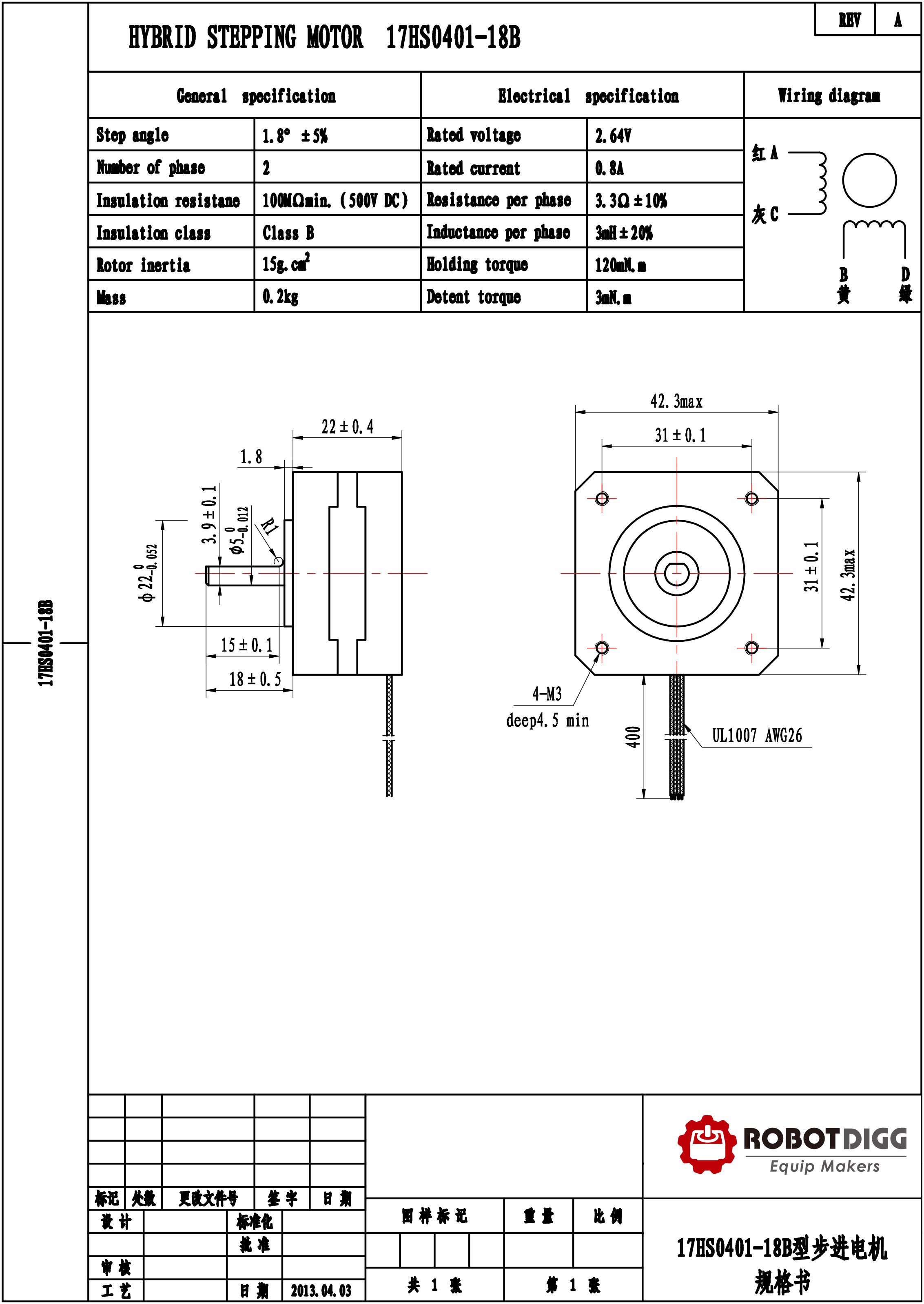
The Stepmotor I chose to use with this is a "pancake" version of the Nema17 as it only has a depth of 24mm thick which isn't much more then the aluminium and mounting plate.
https://www.robotdigg.com/crab/image/2017/11/16/53607a16c76b20940077bf5a94ac0990.jpeg
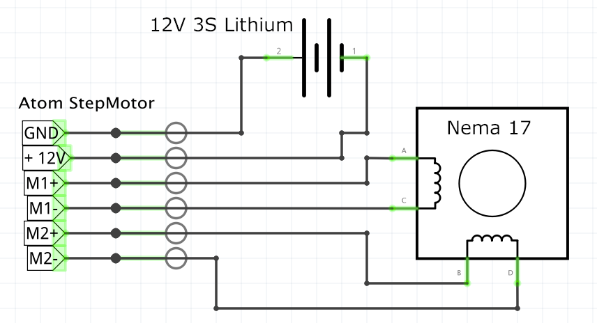
The existing connector is removed and the ends of the wire tinned to stop the strands from spreading out and causing accidental short circuits.
The four wires are checked with a multimeter to find out which pairs are connected together and then each pair is pushed into the Atom Step motor unit and screwed down to secure the wire in place.
Next the Step motor is attached to the top plate using 4 M3x6mm screws.
The Front plate is now attached using 2 M3x6mm Screws make sure the hole under the curved part is at the top.
The Atom Step motor is added and wired as in the schematic diagram, the Atom Lite is push on and they just get pushed in between the sloped parts.
The turntable top piece is printed out and is just pushed onto the shaft of the stepper motor. If the printer is not finely tuned, you may get issues putting the piece of the shaft as the hole is "D" shaped and not round.
OptionalAlso in the download are "Back" boxes which have been designed to push into the 50x50mm gaps in the frame to hold cables and make the design look cleaner underneath. They also have holes for M3 screws to allow them to be secured to the frame.
Controlling the Stepmotor unit.
The Stepmotor unit is designed around the DRV8825 and so only requires three pins to be controlled by the Atom.
The three pins are as follows:
EN - when the pin is pulled high, the DRV8825 is active, when pulled low it is deactivated.
DIR - When pulled low, step motors turn clockwise, when pulled high step motors turn anti clockwise.
STEP - when pulled high for 1.8 seconds and then low, will cause a step motor to move one division (1.8 degrees on a standard Nema17 stepmotor.)
The minimum code required for this in uiflow is as follows.
The only problem with this code is that the turntable will move slowly which is perfect for video photography but for photogrammetry we need to add a pause to allow the photographer to take the photo. For this all you need to do is add a second Wait block for to pause the rotation for the time desired to take a photo.
If we want to automate this (assuming you have the camera support hardware) we can use a relay unit to trigger the camera. the only issue with this is that the second wait needs to be set to allow the camera to save the file before the loop continues.
In this example I have set the initial state of the relay to off outside of the loop to prevent any false firing at the start. To trigger the camera the code immediately turns the relay on and off to represent the press of the trigger button and then waits 3 seconds for the camera to save before continuing the loop.
In Conclusion.I have only shown a basic use for the 1515 extrusion and the Atom Steppermotor unit. The frame can be altered to buy swapping out parts for different lengths of 1515 extrusion or even made more stable by adding a baseplate.
I will leave ideas to you dear reader but please contact me to share your ideas and modifications.
Thank you for taking to time to read all the way through this completed guide.


Comments