


Hardware components | ||||||
 |
| × | 2 | |||
 |
| × | 1 | |||
| × | 1 | ||||
Hello! We're Jeremiah Smith and Ruslan Yarotskiy, a student instrumentation team building a "Do-it-yourself" security system.
Prefabricated security systems can get expensive. Some of the most effective security systems, however, do nothing more than sense that someone is in or near your house, turn a light on, and notify you of their presence. In this project, we accomplish all of that using nothing more than two hobbyists' micro-controllers and about $30 of parts from Amazon. Check out the video below.
Parts:
So how is it done? Let's start with the parts you will need. First, you will need two micro-controllers. We used Particle's photon, as they have internet connectivity very easily integrated into their platform.
You will also need a 3-pin PIR motion sensor. Keyestudio's PIR sensor is one of the cheapest on Amazon, and we have found it to work extremely well and reliably. It has a range of about 10 feet, and a really wide angle of reception.
Next, you are going to need a relay so that you can switch the 120 volt wall power using your Photon. You can get one on Amazon for about $6.00, and a couple minutes on the internet will yield half a dozen "How to" guides of how to wire one to do what we need here. Essentially, you need to be able to plug the relay into your wall, plug a lamp into the relay, and then control the relay by grounding it to your photon with one wire and either applying 3.3 volts or 0.0 volts to a second wire.
This is the cheapest option, but it has a couple of problems which led us to decide against it in favor of Digital Loggers' IOT relay. First, beginners like us have a tendency to blow the cheaper relays, while the IOT relay has built-in surge protection. Second, we didn't want to have to buy electrical plugs, which would have to be wired to the relay to get the clean, enclosed feel that we wanted. Finally, the IOT relay, which is $25 on Adafruit (and Amazon, at the time, though it has since gone up to $29), saves the time of any wiring for the relay. Thus, considering the monetary value of time, we decided it was cheaper to buy the cleaner, more reliable IOT relay.
The other parts you will need for the project you probably already have. You will need some jumper wires, and a lamp (or any kind of light which you can power from your wall).
Setup:We set up the project so that there are two photons, each with a separate circuit only connected through the internet. One photon, the sensing photon, is used to operate the PIR sensor, receiving data and transmitting it to the other photon, the control photon. The control photon receives the signal from the sensing photon and controls the relay (and thus the lamp) accordingly.
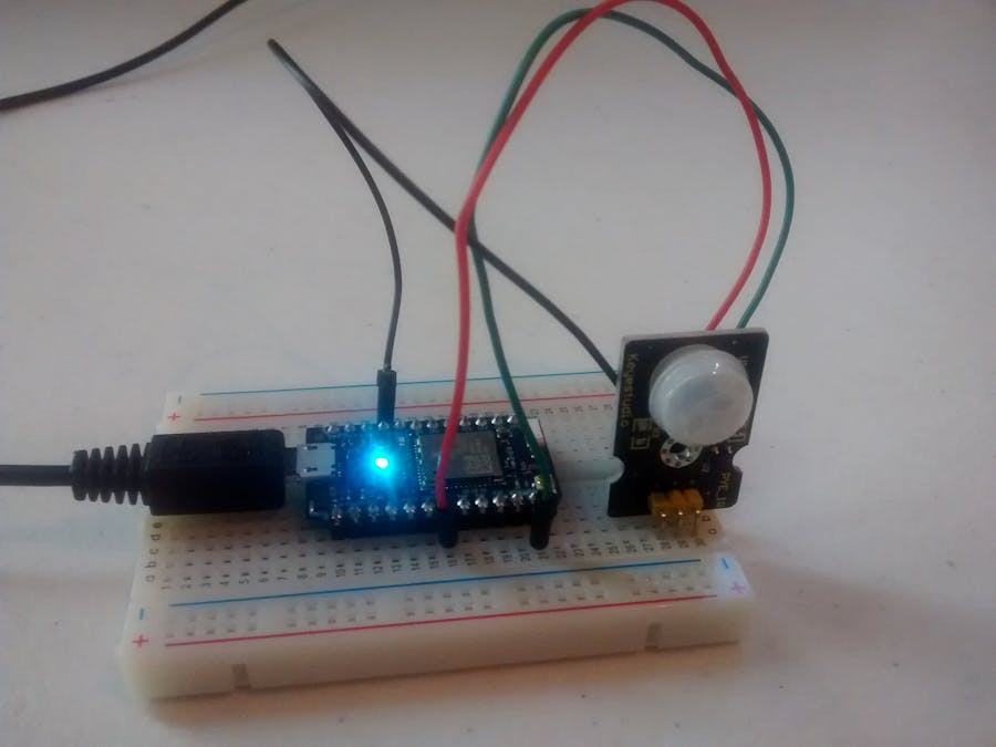
To be more specific, we connected the negative pin on the PIR sensor to a GND pin on the photon, the positive pin to A5, and the "S" (Sensing) pin to A0. On the other photon, we connected the positive input of the relay to D7 and the negative input to GND. We then plugged the lamp into the relay and the relay into the wall. Check out the "Code" section below to see what these pins are doing.
The sensing photon with its three connections to the PIR sensor is shown immediately below. Below it, the control photon and its two connections to the relay are shown.
The exact code can be found in the attachments, but we'll talk you through the general thought process here.
On the sensing photon, A5 is set to digital write a "High" value, providing constant power to the PIR sensor. A0 is set to analog read, taking the actual measurement from the sensor. These reading will vary from 0 to just above 4000, so 2000 ticks is the halfway mark. If the reading is above 2000, the code is set to publish an event to the cloud indicating that the PIR has sensed motion.
On the control photon, pin D7 is set to a digital write. The control photon subscribes to the event published by the sensing photon, and writes "HIGH" whenever the event occurs. At this point, it publishes its own event to the cloud, indicating that the lamp is on. After a delay, it writes "LOW" to D7, turning the lamp off. Again, it uses a publish command to update the data in the cloud.
Once the data from the control photon is in the cloud, the options for what can be done with it are nearly limitless. We do only two things. The main one is to graph the data to be viewed from anywhere in the world so long as we have an internet connection, and you can read about how we did that in the "Graphing" section below. The other is accomplished by a simple subscribe command back on the sensing photon.
In order to confirm to the sensing photon that the control photon has successfully turned on the lamp, we need to establish two-way communication. Thus, we write code to make the sensing photon subscribe to the feed from the control photon. When the sensing photon sees an event, it does a digital write to pin D7. This digital write turns on the on-board LED, visually confirming that the lamp is on.
Graphing: When we leave our house, we want to know if the sensor is being triggered. We thus used a ThingSpeak channel linked to Particle's Webhook ability to get a live graph of the sensor's readings. Check it out HERE. As you can see below, the graph is pretty simple, but it keeps us aware of what is going on at our house whenever we want to look at it.
Conclusion: If you want to set up a basic security system, complete with high-powered lights and online graphing or notifications, hopefully this project will give you some inspiration. It could easily save you some cash, and you have the added benefit of having built the entire system yourself. If you aren't hooked yet, just imagine how neat it would be to walk around your house and have the lights come on automatically.


Comments