


Hardware components | ||||||
 |
| × | 1 | |||
_ztBMuBhMHo.jpg?auto=compress%2Cformat&w=48&h=48&fit=fill&bg=ffffff) |
| × | 1 | |||
Software apps and online services | ||||||
 |
| |||||
In this team project, we will build a pneumatic meter that tells us temperature, humidity and fine dust using Wi-Fi module. To do so, you need to know the Wi-Fi module. I will use the ESP-01, which is less expensive. So please note that other models may be different from my description.
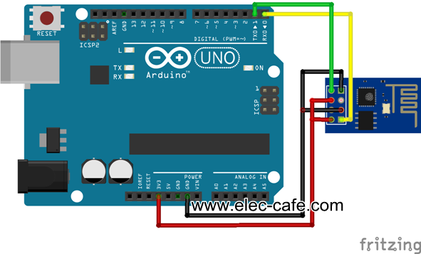
Part 1ESP-01 firmware update must first be performed. To do so, you must connect as follows.
Then download the two files below and store them on the desktop.
Download both files and save them on your desktop, and then unzip them. Then insert the 02 file into the folder where the 01 file is located.
Then open the ESP 8266 file on the desktop to run the esp06_flash_flasher.exe.
If you run a program, there will be a button called Bin. Let's push the button.
Pressing the button opens a window to select the file. We chose the desktop because we saved the files on the desktop.
After selecting the file, set up your own Arduino port and press the download button.
If the following screen is displayed, it is successful. If you don't see the screen below, turn off the Arduino power and try turning it back on, or try downloading the file again.
If the firmware update succeeds, the word 'Leaving' is displayed as follows:
If the firmware update for ESP-01 has been successful, connect to Wi-Fi. First, download the file below and save it on the desktop.
File 03: http://deneb21.tistory.com/attachment/cfile5.uf@236B464B56DECB5503184F.zip
Then run the Arduino IDE, go to Include Library and click the Add ZIP file button to select the downloaded file.
Click on Include Library again and select the newly added 'arduino-ESP8266-master'.
If you perform these steps correctly, the following screen will be displayed:
Disconnect the GPIO 0 line that you initially plugged in before uploading. Then upload and click on the serial monitor.
(Sometimes the upload fails. Most of the time it is due to high power consumption by the ESP-01. Therefore, it is recommended to disconnect ESP-01 when uploading.)
Disconnecting ESP-01To connect ESP-01 to WI-FI, the command must be sent via the serial monitor. To do that, you need to know a simple command.
First, you need to find out if ESP-01 and Arduino are communicating and communicating properly. The command to know this is [ AT ]. If you enter AT and answer OK, it means that the communication is working properly.
ESP-01 is available in three modes:
- [ AT + CWMODE = 1 ] is a command that accesses Wi-Fi.
- [ AT + CWMODE = 2 ] is a command that enables ESP-01 to provide Wi-Fi signals.
- [ AT + CWMODE = 3 ] is the instruction to use both modes simultaneously.
In this project, [ AT + CWMODE = 1 ] is input because ESP-01 needs to be connected to Wi-Fi.
In order to connect ESP-01 to Wi-Fi, Wi-Fi must be searched for and found. Enter the command [ AT + CWLAP ] to read the nearby Wi-Fi.
If you've searched for nearby Wi-Fi, you need to connect to that Wi-Fi. How to connect to WiFi is [ AT + CWJAP = "Name of Wi-Fi you want to connect to" , "Password of Wi-Fi you want to connect to" ].
For example, if your home Wi-Fi name is "PISnet_0359C8" and your password is "12345678", you can send a command by typing [AT + CWJAP = "PISnet_0359C8", "12345678"].
To check if the connection is correct, type [AT + CIFSR]. This command tells you the IP address of the connected WiFi.
Now we know how to connect the ESP-01 to WiFi. Next, I'll show you how to use the DHT11 sensor to send the collected information to your website.
Until now, it was ParkMoonsu! See you next time!
Note: sites and source of the file - http://deneb21.tistory.com/


Comments