/************************************************************************
*
* Test of the Pmod
*
*************************************************************************
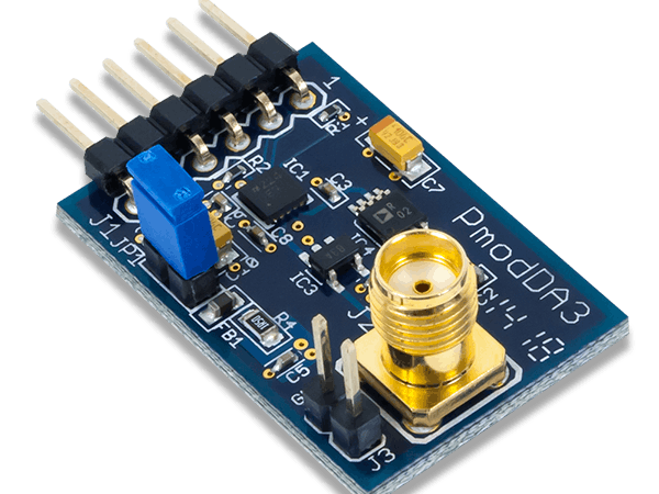
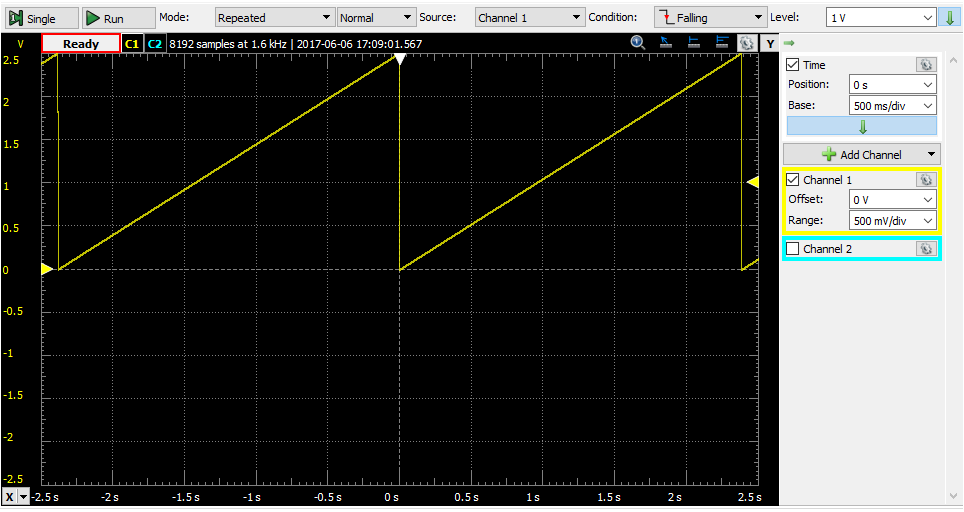
* Description: Pmod_DA3
* The output voltage of the Pmod will change from 0 to 2.5 V to generate a
* triangular signal.
*
*
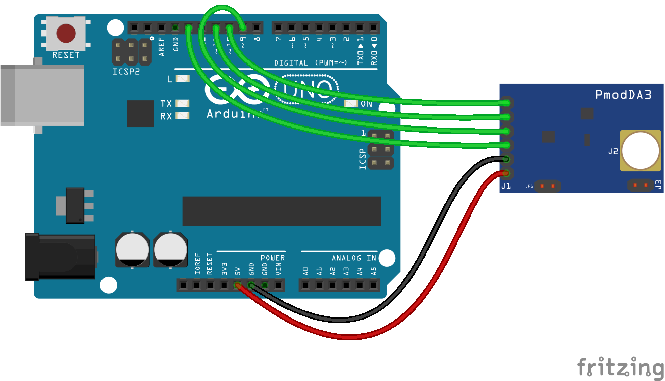
* Material
* 1. Arduino Uno
* 2. Pmod DA3 (do not touch JP1 jumper)
*
************************************************************************/
#define CS 10 // affectation of CS pin
#define LDAC 9 // affectation of LDAC pin
#include <SPI.h> // Include library
int i;
int j;
void setup()
{
Serial.begin(9600); // initialization of serial communication
SPI.begin(); // initialization of SPI port
SPI.setDataMode(SPI_MODE0); // configuration communication SPI in mode 0
SPI.setClockDivider(SPI_CLOCK_DIV16); // configuration of clock at 1MHz
pinMode(CS, OUTPUT);
pinMode(LDAC, OUTPUT);
}
void loop()
{
for (i=0;i<256;i=i+1)
{
for (j=0;j<256;j=j+1)
{
digitalWrite(LDAC, HIGH); // deactivation of LDAC line
digitalWrite(CS, LOW); // activation of CS line
SPI.transfer(i); // send high bits
SPI.transfer(j); // send low bits
digitalWrite(CS, HIGH); // deactivation of CS line
digitalWrite(LDAC, LOW); // activation of LDAC line
/* Period of signal is eround 2,4 s.
* If it is desired to increase it, we can introduce a delay at each passage in the loop
* delay(1); or delayMicroseconds(50);
*/
}
}


_ztBMuBhMHo.jpg?auto=compress%2Cformat&w=48&h=48&fit=fill&bg=ffffff)


Comments