

Hardware components | ||||||
| × | 1 | ||||
 |
| × | 1 | |||
 |
| × | 1 | |||
 |
| × | 10 | |||
 |
| × | 1 | |||
| × | 1 | ||||
Software apps and online services | ||||||
| ||||||
| ||||||
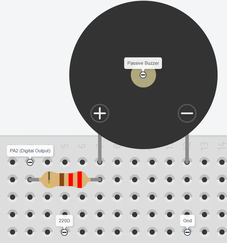
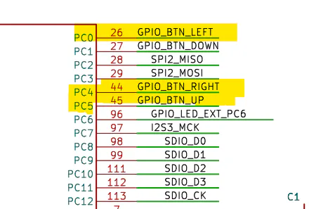
This project is built using the RT-Spark development board with the STM32F407ZGT6 MCU. It focuses on simply producing a frequency by code delays to switch the pin on/off, reading button inputs, remembering states, and generating a beep sound through a passive buzzer.
Three push buttons are used to control the system. One button plays the sound, while the other two buttons increase or decrease the frequency of the tone. Instead of using hardware timers, the tone is generated by toggling a GPIO pin with the help of a microsecond delay function. This allows students to understand how timing affects signal generation in embedded systems.
Note: A software-produced frequency is always inferior to one that is produced from a hardware such as, timer because a code always involves a function overhead. It may typically be a nano-microsecond delay, but in terms of accuracy, especially in time-constrained applications, it is not recommended and it's better off to use a hardware that doesn't bother the CPU too much, saving the CPU's resources for other tasks.
HARDWARE CONFIGURATIONTone Generation
The picture shown below is the heart of the frequency production, in which the function creates/mimics a square wave by repeatedly changing the state of the output pin (PA2) and adding delays between transitions. The duration is optional for it is only used as a loop for how many times the period should repeat.
The function "update_buttons" simply checks the button states to prevent the logic from executing continuously by holding a button or in short, debouncing that is done in software rather than hardware.
Because the square wave is produced purely from a software side, it is prone to inaccuracy, typically adding nano-microseconds delay or worse due to function overhead, especially when the delay function itself is also heavily in software side rather hardware side, which is shown below.
Here, it shows that there is a slight ramp, both from rising and falling-edge due to function overhead, an expected 100µs period/cycle becomes approximately 115µs and a slight inconsistency in both voltage state.
CONCLUSION - WHAT HAVE WE LEARNED & WHAT COULD HAVE BEEN DONEThis project successfully demonstrates how software delays, button inputs, and GPIO toggling work together to control a passive buzzer. While using software loops serves as an effective educational tool to understand signal timing, testing proves exactly why software-driven frequencies are inferior for real-world applications. Because the CPU must process every microsecond delay and button check sequentially, function overhead adds an extra 15µs to the target 100µs period and distorts the waveform.
To achieve near-perfect accuracy, the system should transition from software loops to the STM32F407ZGT6’s built-in hardware timers. By utilizing a timer in PWM mode, the microcontroller generates the square wave using its internal hardware clock, completely eliminating software instruction lag and producing the exact target frequency. Best of all, once initialized, the hardware timer runs autonomously in the background, meaning the CPU barely has to deal with the signal generation at all. This frees the processor from wasting cycles counting down delays or flipping pins, saving its resources entirely for other tasks.
In the same way, moving the button debouncing from software routines to hardware filters like RC circuits would clean up input signals instantly without forcing the CPU to pause and wait out contact bounce. Ultimately, while software delays are useful for demonstrating basic concepts, leveraging dedicated hardware peripherals is the only way to ensure perfect signal accuracy while keeping the CPU completely unburdened.


Comments