


Hardware components | ||||||
 |
| × | 1 | |||
 |
| × | 4 | |||
 |
| × | 1 | |||
 |
| × | 1 | |||
| × | 1 | ||||
| × | 1 | ||||
Software apps and online services | ||||||
| ||||||
| ||||||
This activity we built a simple sound generator using an STM32 microcontroller. The system uses three push buttons and a speaker module.
The first button increases the frequency of the sound, the second button plays the tone, and the third button decreases the frequency. By pressing the buttons, different sound frequencies can be produced through the speaker.
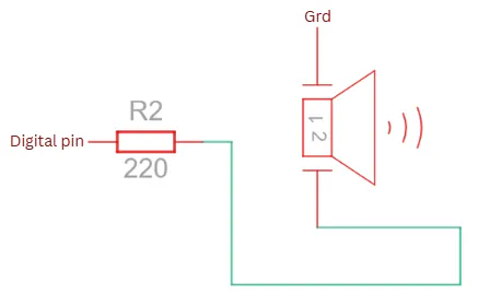
First, the hardware components were connected according to the provided schematic diagram. The three push buttons were connected to GPIO input pins, while the speaker was connected to an output pin.
GPIO ConfigurationsThe switch pins were configured as pull-up inputs, while the speaker pin was configured as a push-pull output.
The speaker was connected to PA2, while the three push buttons were connected to PC0, PC4, and PC5 as input pins.
Results and DiscussionThe activity successfully generated tones with different frequencies. The buttons were able to control the frequency as intended.
The measured frequency values were very close to the expected values. Small differences were observed, which may have been caused by processing delays and hardware limitations.
The speaker produced audible tones at different frequencies, showing that the program worked correctly.
Test the Output SignalThe generated signals were tested using a logic analyzer or oscilloscope.
Different frequency values were measured and compared with their expected values.
Frequency: 1k Hz
Expected Period: 1ms/cycle
The measured period was 1.02 ms, which is very close to the expected 1 ms. This means the circuit was able to produce the correct frequency with only a very small difference.
Frequency: 2.5k Hz
Expected Period: 400us/cycle
The measured result was 414 µs instead of 400 µs. Even though it was slightly higher than expected, the output was still close to the target frequency.
Frequency: 5k Hz
Expected Period: 200us/cycle
The measured period was 216 µs, while the expected value was 200 µs. The small difference may be due to delays in the program, but the output still worked properly.
Frequency: 8k Hz
Expected Period: 125us/cycle
The measured period was 140 µs compared to the expected 125 µs. The result shows that the system was still able to generate a high-frequency signal successfully.
Frequency: 10k Hz
Expected Period: 100us/cycle
The measured period was 116 µs instead of 100 µs. Although there was a slight difference, the generated tone was still close to the desired frequency.
Frequency: 100 Hz
Expected Period: 10us/cycle
The measured period was 10.0 ms, which matched the expected value very closely. This shows that the system can also produce accurate low-frequency signals.
Frequency: 250 Hz
Expected Period: 4ms/cycle
The measured period was 4.00 ms, which was exactly the same as the expected value. This means the output frequency was very accurate.
Frequency: 500 Hz
Expected Period: 2ms/cycle
The measured result was 2.01 ms, which is almost the same as the expected 2 ms. The difference is very small and does not significantly affect the output.
Frequency: 800 Hz
Expected Period: 1.25ms/cycle
The measured period was 1.26 ms, while the expected value was 1.25 ms. Since the values are nearly identical, the frequency generation was successful.
The results show that the generated frequencies were close to the expected values, indicating that the tone generator was functioning properly.
Video DemoThis video shows the sound generator project in action. The buttons were used to change the sound frequency and play tones through the speaker.
ConclusionThe system was able to generate tones through a speaker and adjust the frequency using button controls. Through this activity, I learned how square wave signals are generated, how GPIO pins are configured, and how user inputs can be used to control output devices.


Comments