

Hardware components | ||||||
 |
| × | 1 | |||
 |
| × | 2 | |||
 |
| × | 10 | |||
| × | 1 | ||||
 |
| × | 1 | |||
| × | 1 | ||||
Software apps and online services | ||||||
| ||||||
This activity focused on using the Analog-to-Digital Converter (ADC) of the RT-Spark development board to measure the voltage of a coin cell battery and the USB power supply. A voltage divider circuit was implemented to safely scale the input voltage before it was applied to the ADC input.
Project OverviewThe STM32 ADC can only measure voltages within its reference voltage range. Since the USB supply voltage is approximately 5V, directly connecting it to the ADC would exceed the maximum input voltage. To address this limitation, a voltage divider consisting of two high-value resistors was used to scale the voltage down to a safe level.
In this project, the ADC built into the STM32F407ZGT6 microcontroller on the RT-Spark board was used to measure input voltages. The ADC converts the analog voltage into a digital value ranging from 0 to 4095 (12-bit resolution), which can then be translated into an actual voltage through software calculations.
ADC SetupFirst, create a new STM32 project using STM32CubeIDE.
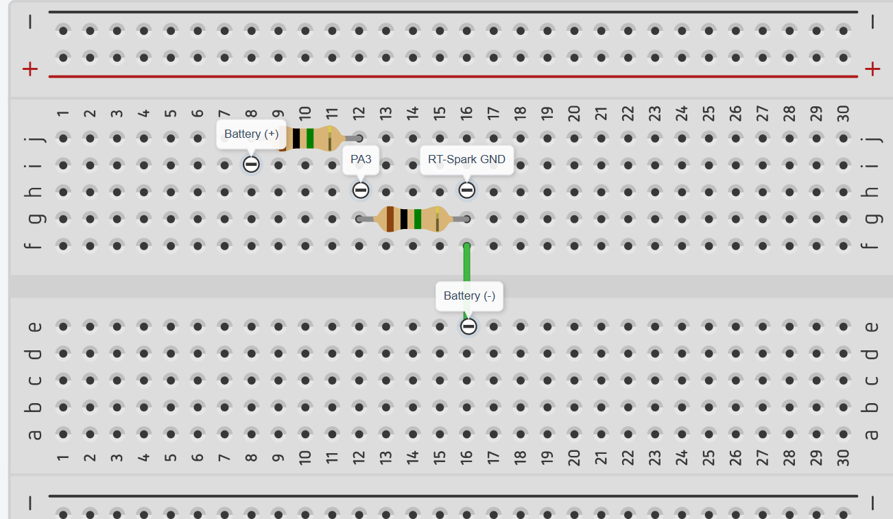
The ADC was then configured by enabling ADC1 and assigning pin PA3 as the analog input channel used for voltage measurements.
Open Analog settings from the left sidebar and set PA3 to ADC1 Channel 3, keep the default GPIO settings, use a Clock Prescaler of 8, set the Sampling Time to 480 Cycles, and disable Continuous Conversion Mode. Then generate code for the project.
The voltage divider was connected between the voltage source and ADC input pin PA3.
The battery voltage was first measured using a digital multimeter.
- VBattery = 3.059 V
- VADCIn = 1.513 V
- VRefH = 3.277 V
After running the provided firmware, the ADC calculated the battery voltage as:
- ADC Computed Voltage (vbat) = 3.026 V
The ADC measurement closely matched the multimeter reading, demonstrating good accuracy.
Resistor MeasurementsThe actual resistor values were measured using a multimeter:
- R1 = 986, 312 Ω
- R2 = 977, 291 Ω
Based on these measured values, the calculated scale factor was:
- Scale Factor = 2.009230618
The firmware was updated using the measured resistor values. After calibration:
- Measured Battery Voltage = 3.059 V
- Calculated Battery Voltage = 3.008 V
The resulting error was:
- Error = 0.051 V (51 mV)
This small error indicates that the system achieved a high level of measurement accuracy.
Measurements Without AveragingFive consecutive battery voltage measurements were recorded:
- vbat(1) = 2.98V
- vbat(2) = 2.87V
- vbat(3) = 2.95V
- vbat(4) = 3.019V
- vbat(5) = 3.03V
The measured voltages were not constant and shows noticeable variations between readings.
Measurements With 10-Sample AveragingThe firmware was modified to average ten ADC samples before calculating the voltage.
Five measurements were recorded:
- vbat(1) = 3.015V
- vbat(2) = 3.013V
- vbat(3) = 3.016V
- vbat(4) = 3.012V
- vbat(5) = 3.011V
Small variations were still present, but the readings became significantly more consistent. The averaging process reduced noise and produced more stable measurements.
USB Voltage MeasurementsThe USB supply voltage was measured using a multimeter.
- VUSB = 5.05 V
- VBatDiv = 2.407 V
The voltage divider successfully reduced the USB voltage to a level that could be safely measured by the STM32 ADC.
Results and DiscussionThe experiment showed how an ADC and a voltage divider can be used to measure battery and USB voltages using an STM32F407ZGT6 microcontroller. It was observed that the actual resistor values were slightly different from their rated values, which affected the voltage calculations. After updating the code with the measured resistor values, the voltage readings became more accurate.
The results showed that using the actual resistor values and applying software averaging improved the accuracy and stability of the measurements. Overall, the activity provided hands-on experience with ADC configuration, voltage divider circuits, voltage measurement, and basic signal processing in embedded systems.


Comments