

Hardware components | ||||||
| × | 1 | ||||
 |
| × | 1 | |||
 |
| × | 1 | |||
 |
| × | 1 | |||
 |
| × | 1 | |||
 |
| × | 1 | |||
 |
| × | 1 | |||
Software apps and online services | ||||||
| ||||||
| ||||||
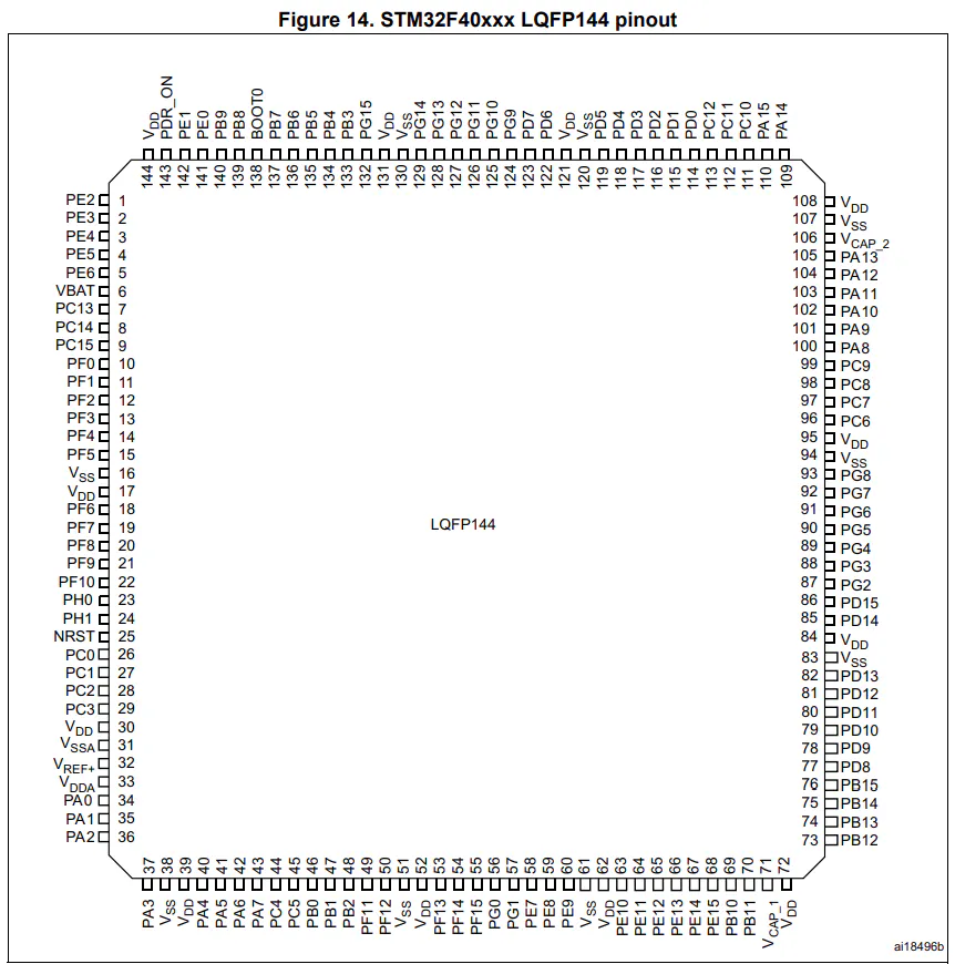
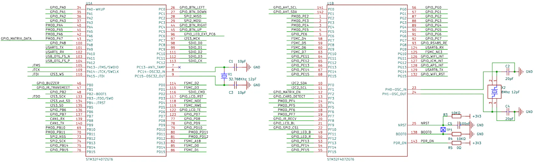
The RT-Spark, or “Spark-1, ” is a development board created by RT-Thread. It is powered by the STM32F407ZGT6 microcontroller and includes several built-in features like Wi-Fi, a buzzer, an SD card slot, and an LED matrix. One of the main parts of the board is its built-in LCD screen.
This project focuses on using the LCD screen. The display has a size of 240×240 pixels and connects to the microcontroller using the FSMC, which helps send data faster and makes the screen more responsive.
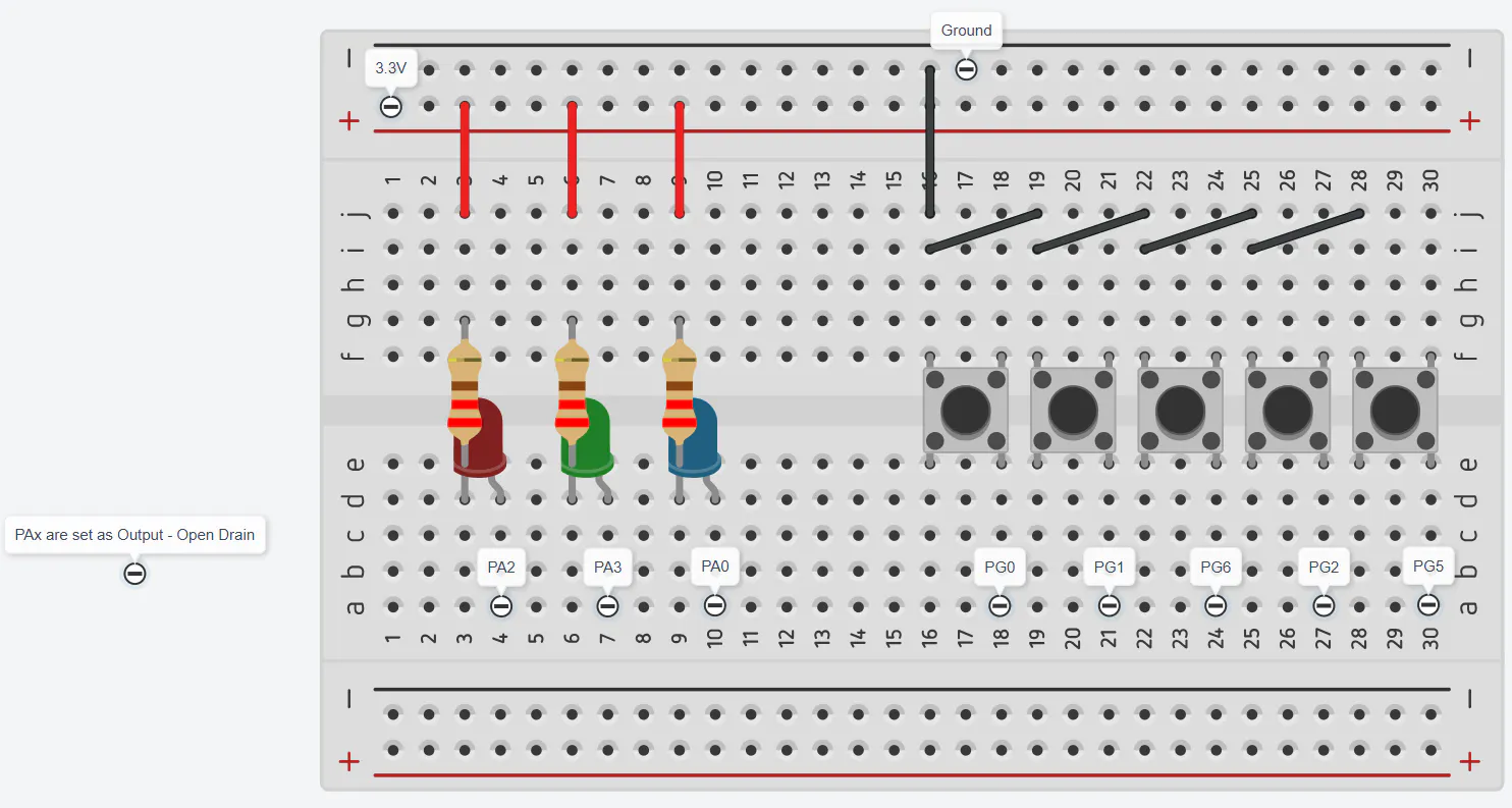
To add user control, five push buttons are used. These buttons allow the user to change the content shown on the screen instantly. In addition, three LEDs, or a single RGB LED, are used to show simple signals or responses based on what the user does.
By combining the screen, buttons, and LEDs, the project shows how the Spark-1 can be used to build a basic interactive system. It explains how input and output work together and how a simple user interface can be created in an embedded system.
BACKLIGHT BUILT-IN LCD
Before moving on to the next steps, it is best to first check if the built-in LCD is still working. If not, you might spend a lot of time troubleshooting without getting any results.
- First, create a new STM32 Project, choose the STM32F407ZGT6 MCU.
- Next, find the backlight pin and configure it as an output. After that, generate the CubeMX code and set the pin to turn on.
The LCD backlight should light up. Meaning, the backlight is fine, but not yet sure for the LCD.
CONFIGURING THE PERIPHERAL COMMUNICATION FOR THE BUILT-IN LCD
- First, find the LCD reset pin and configure it as an output. Then repeat the same steps that were done for the LCD backlight pin.
- Next, set up the FSMC so it can communicate with the LCD interface. Once this is done, generate or update the CubeMX code.
CONFIGURING THE PERIPHERAL COMMUNICATION FOR THE BUILT-IN LCD
The built-in LCD uses the ST7789 v3 driver and communicates through an 8080 parallel interface. To enable communication, the MCU must be configured to use its FSMC (Flexible Static Memory Controller) peripheral, which allows it to interface properly with the LCD.
- Start by locating the LCD’s reset pin and configuring it as an output. Then initialize it using the same approach as the LCD backlight pin to ensure proper control of the display reset operation.
- Next, configure the FSMC to interface with the LCD. Once configured, generate the initialization code using CubeMX to apply the settings.
Two ways to usethe LCD
There are two main approaches to using the built-in LCD. The first is a simpler, guided method that abstracts most of the low-level setup. The second is a manual approach, where you handle everything yourself—controlling the backlight, performing the reset sequence, initializing the display, and writing pixel data one by one.
The code from the previous steps is part of this manual method, specifically handling the LCD backlight configuration.
FINAL OUTPUT


Comments