

Hardware components | ||||||
 |
| × | 5 | |||
 |
| × | 20 | |||
 |
| × | 3 | |||
 |
| × | 1 | |||
 |
| × | 3 | |||
| × | 1 | ||||
 |
| × | 5 | |||
Software apps and online services | ||||||
| ||||||
| ||||||
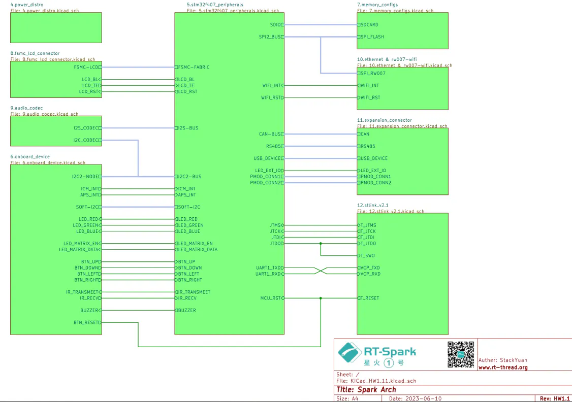
RT-SPARK (SPARK-1) RT-THREAD DEVELOPMENT BOARD
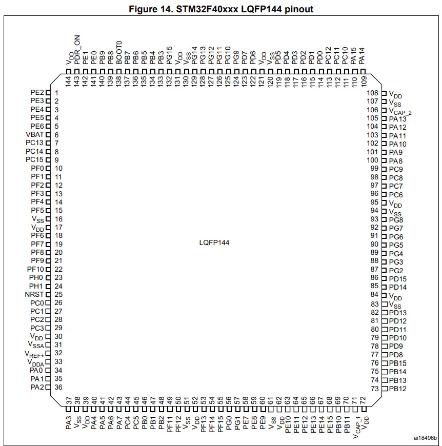
The RT-Spark, or what they call "Spark-1", is a development board from RT-Thread that runs on the STM32F407ZGT6 microcontroller. It comes with a lot of built-in stuff like Wi-Fi, a buzzer, SD card slot, LED matrix, and the one we care about the most for this project — the built-in LCD screen.The LCD has a 240x240 resolution and uses the ST7789 v3 driver chip. It doesn't use the usual SPI or I2C — instead it talks to the MCU through something called FSMC (Flexible Static Memory Controller) using an 8080 parallel port interface. That's what makes it a bit more complicated to set up compared to regular displays.For this project, aside from the LCD, we also added 5 momentary push buttons for user input, and 3 separate LEDs (Red, Green, Blue) that light up depending on which button you press.
STEP 1 — MAKING SURE THE LCD BACKLIGHT WORKS
Before doing anything else, I had to check if the LCD backlight was actually working. If you skip this and go straight to the code, you might spend a lot of time debugging something that's actually a hardware problem.Here's what I did:
1.1 Create a New Project in STM32CubeMX.
1.2. Searched for STM32F407ZGT6 and selected it.
1.3. Go to Project Manager. Type your desired Project Name, after that, change the Toolchain / IDE to STM32CubeIDE. Then, click GENERATE CODE.
1.4. After you clicked it, this will appear.
1.5.
STEP 2 — Look for the.ioc file. Inside the.ioc file (CubeMX), I looked for the LCD_BL pin and set it as GPIO_Output, then labeled it LCD_BL.
OUTPUT: If the backlight turns on, that means the hardware is fine. The LCD screen itself might still be blank at this point — that's normal, we haven't initialized it yet.
STEP 3 — SETTING UP FSMC FOR THE LCDSince the LCD uses the 8080 parallel interface, I had to configure the FSMC peripheral in CubeMX so the MCU can actually communicate with it.
- Opened the.ioc file again
- Went to Connectivity → FSMC on the left panel
- Set the configuration like this:
Note: Other green color appeared because you configured FSMC.
Step 4 — DOWNLOADING AND ADDING THE LCD LIBRARY
Writing the LCD driver from scratch would take forever, so I used a ready-made bare-metal library instead. The official RT-Thread SDK has one, but it requires RTOS which we're not using here. So I used this bare-metal version:
Download link:https://sendgb.com/M8kq5c23FwC
After downloading and extracting the zip:
- Copied all.h files into my project's Core/Inc folder
- Copied all.c files into Core/Src
- Refreshed both folders in STM32CubeIDE by right-clicking them and clicking Refresh
Once that's done, you get access to functions like:
drv_lcd_init()— sets up the LCDlcd_clear(COLOR)— wipes the screenlcd_set_color(bg, fg)— sets your text and background colorslcd_show_string(x, y, size, "text")— actually prints text on screen
STEP 5— WIRING THE SWITCHES AND LEDsSwitch Pin Assignments (GPIOG — internal pull-up):
LED Pin Assignments (GPIOA — active low):
Actual Breadboard Circuit where it connects to RT-Spark:
FINAL OUTPUT:


Comments