

The RT-Spark Board has a microcontroller with different built in components like LEDs, Buzzers, Control Buttons, Display, Light and more. In this project, my LED follows a loop where the first Built in LED toggles on and the second follows, then the Built in LED toggles off and the second LED also follows which loops to make a blinking effect, on and off.
This project uses the following to work:
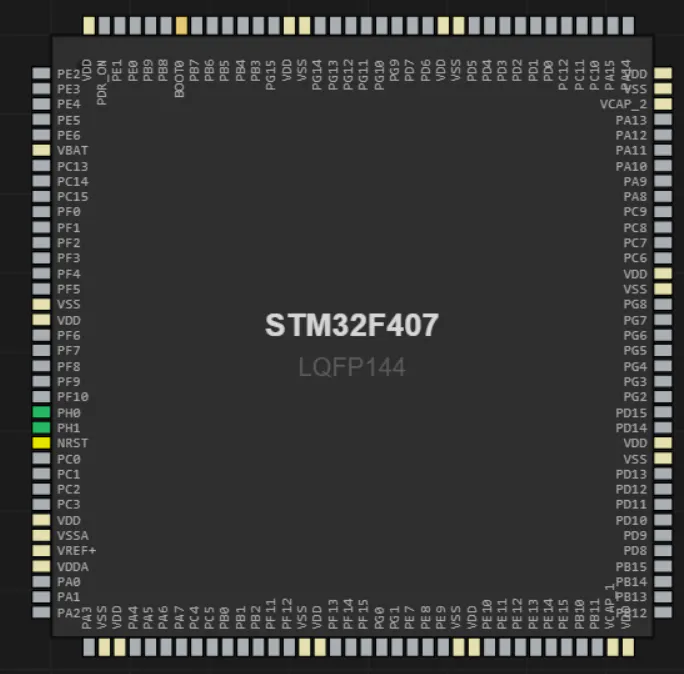
- RT‐Spark (STM32F407ZGT6)
- USB cable
- Windows PC
- software STM32CubeIDE
Step 1 - Install:
- Search STM32CubeIDE and STM32CubeMX and download them, sign up for an account on the website if necessary. Then install them with just the default and recommended settings prepared by the installer for you.
Step 2 - Create the Project:
- In STM32CubeMX, create a new project and put the Commercial Part Number "STM32F407ZGT6", these should display on the right, click on it and click Start Project.
- This should get you to the Pinout & Configuration Tab. Below the screen you can see a search bar, click on it and search for PF11 and PF12. Tap on those two pins when you find them and set as GPIO_Output.
- On the left side of the screen you should also see a search bar. Search for GPIO you should see on the configuration the pins you chose. Now click on them on that list and scroll down on their configuration, set the maximum output speed to medium for both pins.
- Next up, go to the Project Manager tab. Set your project name. Set the Project Location where you want. And set the Toolchain to STM32CubeIDE then finally above click on Generate Code. Wait for it to generate until you can see the Open Project button, click on that.
- That should get you to the IDE with your project which shows Project Explorer on the left. Expand this and go to Core -> Src -> main.c.
- Finally, look for the part of the code which says:
while (1)
{
/* USER CODE END WHILE */
/* USER CODE BEGIN 3 */
}
and turn it to this:
while (1)
{
/* USER CODE END WHILE */
HAL_GPIO_TogglePin(GPIOF, GPIO_PIN_11);
HAL_Delay(500);
HAL_GPIO_TogglePin(GPIOF, GPIO_PIN_12);
HAL_Delay(500);
/* USER CODE BEGIN 3 */
}
at the end, just connect your USB Cable from your Computer to the USB-DBG Input of your RT-Spark Microcontroller. Then on STM32CubeIDE click on the hammer button above and click on the green play button at the side to send the data to the Microcontroller and you should see the green and red small LED blink and blink.
How to Upload to Github:- Create a Github account or Login to your Github account and create a new repository. Most options should not matter, just go with the default options set by Github, you just set the name of your liking like "rt-spark-blink-led" for example.
- Download & Install Git: Git - Install for Windows
- From your Github Repository, you should see repository URL that looks like "https://github.com/yourname/rt-spark-blink-led.git" copy that for later.
- Go to the folder where you put your STM32CubeMX project in from earlier, example: "C:\Users\User\Documents\Sample_Name_STM32_Blink_LED"
- Copy that path for the next step
- Open CMD and put this command in with what I made you copy like this:
cd C:\Users\User\Documents\Sample_Name_STM32_Blink_LED- Input these in the CMD too:
git init
git add .
git commit -m "Initial commit: STM32F407ZGT6 Blink LED"- Then input this too with the Github Repository I made you copy earlier:
git remote add origin https://github.com/yourname/rt-spark-blink-led.git
git branch -M main
git push -u origin main- After that, you'll be asked to log-in, you can login using browser to connect the Github.
- Finally, refresh your Github and it should updated there like this:
Github Repository Link: Melvin-Raphael/rt-spark-blink-led


Comments