


Hardware components | ||||||
_ztBMuBhMHo.jpg?auto=compress%2Cformat&w=48&h=48&fit=fill&bg=ffffff) |
| × | 1 | |||
 |
| × | 1 | |||
 |
| × | 1 | |||
 |
| × | 1 | |||
 |
| × | 1 | |||
 |
| × | 1 | |||
 |
| × | 1 | |||
 |
| × | 1 | |||
 |
| × | 1 | |||
 |
| × | 1 | |||
 |
| × | 1 | |||
 |
| × | 1 | |||
 |
| × | 1 | |||
Software apps and online services | ||||||
 |
| |||||
Hand tools and fabrication machines | ||||||
 |
| |||||
 |
| |||||
 |
| |||||
Every year, mountain sports enthusiasts face life-threatening situations in avalanches and at high altitudes. When buried under snow or experiencing respiratory distress, every second counts. Traditional rescue methods rely on external help arriving quickly, but what if the athlete could have an automated life-support system right on their body?
This question inspired SkiOx - a comprehensive IoT platform designed to automatically monitor physiological parameters and deliver emergency oxygen when it matters most.
SkiOx is a portable rescue device that continuously monitors an athlete's vital signs (SpO₂ and heart rate) and automatically triggers oxygen delivery when critical thresholds are detected. The system consists of:
- Wearable Hardware: An Arduino-based device with physiological sensors, housed in a protective 3D-printed enclosure
- Emergency Oxygen System: A 12V solenoid valve connected to an oxygen supply (simulated with water in our prototype)
- Real-Time Monitoring: Bluetooth connectivity sends data to a backend server
- Web Dashboard: Rescuers can monitor multiple athletes simultaneously through an Angular-based Progressive Web App
When an athlete presses the emergency button or when sensors detect dangerous physiological conditions, the system activates automatically, potentially buying critical minutes until rescue teams arrive.
The system architecture follows a modular design, separating concerns between hardware control, data management, and user interfaces. This enables independent scaling and maintenance of each component.
ObjectivesThe SkiOx project aims to achieve the following primary objectives:
- Autonomous Physiological Monitoring: Provide a self-contained system capable of measuring critical physiological parameters (SpO₂, heart rate, etc.)
- Automatic Emergency Response: Trigger automatic oxygen distribution when respiratory distress is detected
- Real-Time Data Transmission: Communicate data in real-time to a centralized platform for supervision and archiving
- Rescue Team Support: Facilitate intervention by mountain rescue teams through precise, real-time data.
- Modular IoT Platform: Offer an extensible and modular IoT integration platform.
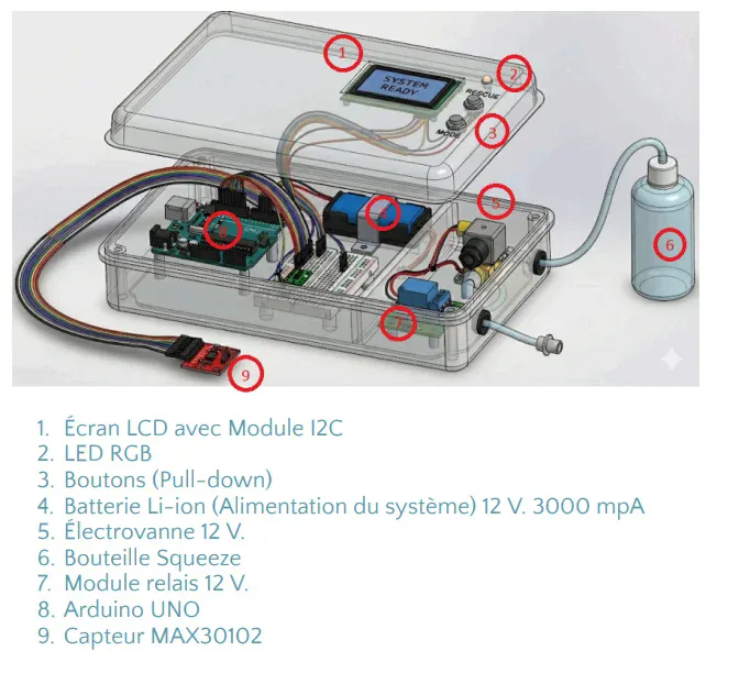
Hardware Components
Operating Principle
The rescue system consists of several distinct elements:
- An electronic measurement and control unit based on Arduino Uno
- A physiological parameter sensor (MAX30102 sensor for SpO₂ and heart rate, complemented by simulation potentiometers)
- A Bluetooth HC-05 communication module for transmitting measurements to a backend system
- A status indication subsystem (RGB LED and LCD I2C screen)
- A rescue activation button and a mode selection button
- A 12V solenoid valve controlled by Arduino to regulate fluid
- A 12V relay module and 12.6V 3000mAh Li-ion battery for power sup
- A squeeze bottle connected to the solenoid valve via pneumatic tubes
Hardware Wiring & Integration
Analog Inputs
A3: Potentiometer 2 (simulated oxygen level)
In "real sensor" mode, A0–A2 can be ignored by software or repurposed for other measurements.
I2C Bus
- SDA (A4 on Arduino Uno) → SDA LCD + SDA MAX30102
- SCL (A6 on Arduino Uno) → SCL LCD + SCL MAX30102
Both modules share the same I2C bus; their I2C addresses must be compatible.
Digital Connection
- D2: Rescue activation button (pull-down)
- D3: Mode selection button (simulation/real sensor)
- D4: RGB LED – red channel (via resistor)
- D5: RGB LED – green channel (via resistor)
- D6: Relay module control (relay IN 12V)
- D10: Arduino RX ← HC-05 TX (via voltage divider if necessary for 3.3V)
- D11: Arduino TX → HC-05 RX
Power Supply
5V Arduino
- Powers Arduino, LCD, MAX30102, HC-05, RGB LED, buttons, etc.
- Currents remain modest (several hundred mA maximum)
12V (Li-ion Battery)
- Powers solenoid valve via relay modul
- Relay is commanded at 5V (Arduino side), but switches 12V line (power side)
Ground Separation:
- Ground (GND) of 5V section (Arduino) must be connected to 12V ground for common signal reference, while maintaining galvanic isolation between control and power sides via relay.
MAX30102 Sensor Integration
Description
The MAX30102 is an integrated optical sensor incorporating red and infrared LEDs and a photodetector, designed to measure blood oxygen saturation (SpO₂) and heart rate. It communicates via I²C bus (SDA/SCL) and operates at 3.3–5V[4].
Electrical Connections
Typical module pinout:
- VIN: 3.3V or 5V (depending on module
- GND: Arduino GND
- SCL: Arduino SCL (A5)
- SDA: Arduino SDA (A4)
- INT (optional): Arduino digital input (e.g., D7) for managing interrupts
Software Integration
In simulation mode, the code simply reads analog values A0–A2. In real sensor mode, the code:
- Initializes MAX30102 on the I2C bus
- Configures sampling frequency, LED currents, etc.
- Periodically reads SpO₂ and heart rate values from the sensor
- Updates internal variables replacing values from potentiometers
Bluetooth HC-05 Module
Role
The HC-05 module ensures communication between Arduino and a backend system (computer, smartphone, server, etc.) via Bluetooth serial (SPP profile). SpO₂, heart rate, battery level, and system status values are transmitted at regular intervals.
Connection
- VCC: 5V Arduino
- GND: Arduino GND
- TX: Arduino RX (D10, possibly via voltage divider if necessary)
- RX: Arduino TX (D11)
Configuration
- Default Name: "HC-05
- Typical Baud Rate: 9600 bauds
Power Supply & Solenoid Valve Control
Power Architecture
- Li-ion Battery 12.6V – 3000mAh: Provides necessary voltage to solenoid valve with adapted protection system (BMS
- 12V Relay Module: Coil commanded at 5V by Arduino (output D6), power contacts switching 12V line
- 12V Solenoid Valve: Typical normally-closed (NC) operation, opens when coil is powered at 12V
Control Logic
When:
- System is On
- Rescue button is pressed
- Physiological values exceed critical thresholds (low SpO₂, abnormal heart rate, etc.)
- Arduino activates output D6 → relay module closes contact → 12V solenoid valve is powered → fluid (water/simulated oxygen) flows from the bottle.
Activation duration can be :
- Fixed time (e.g., 5–10 seconds, configurable)
- Function of patient status (longer if parameters remain critical)
Hardware User Interface
RGB LED (System Status)
Red: System OFF or in error
- Red: System OFF or in error
- Green: System ON and operational
Implementation
- D4: Red channel of LED (via resistor)
- D5: Green channel of LED (via resistor)
LCD I2C Screen
Displays:
- Line 1: SpO₂ (real or simulated), Heart rate (real or simulated)
- Line 2: System status: "MODE: SIMU" or "MODE: REAL"
The LCD is connected via I2C and powered at 5V.
Buttons
- Rescue Button (D2): Short press for activation/deactivation of rescue mode
- Mode Selection Button (D3): Short press to toggle between SIMULATION and SENSOR modes
Hardware-Software Logic
Initialization
- Initialize I/O ports (LED, relay, buttons)
- Initialize I2C bu
- Initialize LCD screen
- Initialize Bluetooth HC-05 module (Serial)
- Initialize MAX30102 (if available)
- Display startup screen
- Set LED to red (system OFF)
Hardware Assembly Procedure
Step 1 – Component Preparatio
- Verify presence of all components
- Prepare tools: soldering iron, screwdrivers, wire cutters, wire strippers, multimeter, 3D printer if necessary
Step 2 – Low Voltage (5V) Wiring
- Mount Arduino and modules on breadboard or PCB
- Make common 5V and GND connection
- Connect SDA/SCL, TX/RX, analog inputs, LED/relay outputs, buttons
Step 3 – Power Wiring (12V)
- Connect 12.6V battery to relay module
- Connect relay output to solenoid valv
- Connect solenoid valve other terminal to 12V GND
- Verify connections with multimeter while powered off
Step 4 – Arduino Programming
- Load firmware on Arduino via Arduino IDE
- Verify potentiometer and/or MAX30102 reading
- Verify LCD display and Bluetooth communication
- Verify RGB LED control and relay activation
Step 5 – Enclosure Integration
- 3D-print enclosure or use standard enclosure
- Secure components insid
- Route pneumatic tubes externally and connect to squeeze bottle
- Close enclosure and perform complete functional test
Mechanical Considerations
Enclosure Objectives
- Protect electronic components from shocks and moistur
- Consolidate in same enclosure: Arduino, modules, LCD screen, RGB LED, buttons, battery
- Provide clear and ergonomic interface for end user
Recommendations
- Design two-part enclosure (cover + base) for easy acces
- Provide openings for LCD screen, RGB LED, buttons, charging connectors, tube passages
- Integrate internal supports for securing Arduino board, relay module, battery
- Use screws or clips for enclosure closure
Logic of Operation
The system operates according to the following sequence:
- Initialization: The system powers on; Arduino initializes sensors, LCD screen, RGB LED, and Bluetooth connection
- Mode Selection: The user selects "simulation mode" (potentiometers) or "real sensor mode" (MAX30102) via a dedicated butto
- Emergency Activation: When an athlete is in distress, the rescue button is pressed to activate the system
- Decision Logic: Based on measurements (SpO₂, heart rate, "battery level" simulating energy state) and software logic, Arduino decides whether to trigger the solenoid valve or keep it closed
- Data Transmission: Measured data is displayed on the LCD screen and transmitted via Bluetooth HC-05 to the backend for processing and recording
- System Status: Overall system state (ON/OFF) is indicated by RGB LED: red = system offline, green = system operational
The SkiOx project relies on a robust full-stack environment designed for reliability and scalability.
Technology StackThe development and deployment environment is based on the following technologies:
- Node.js (LTS): JavaScript runtime for server-side execution
- npm: Dependency manager.
- Docker Desktop: Container orchestration (MySQL).
- Angular: Modern frontend framework.
- MySQL: Relational database for persistence.
- Express.js: Web framework for Node.js.
- Swagger UI: Interactive API documentation.
- TypeScript: Typed JavaScript for both frontend and backend to ensure code safety.
Services & PortsThe full-stack architecture requires the simultaneous initialization of four distinct services:
Data Infrastructure (Backend Service)
The persistence layer is managed through Docker. Ideally, run this command from the Back/ directory to initialize the MySQL instance and phpMyAdmin:
This command automatically:
- Initializes the MySQL server with the schema defined in SQL scripts.
- Loads test data (seeds).
- Deploys the phpMyAdmin administration interface.
API Server (Backend)The core logic is a RESTful API (Node.js/Express). To launch in development mode with hot-reload enabled:
For production environments:
User Interface (Frontend)The Angular-based Progressive Web Application (PWA) is launched from the IHM/ directory:
Interactive Technical DocumentationGenerated via Swagger UI, accessible by running:
The project follows a modular directory hierarchy:
SkiOx/
├── Back/ # Server-side logic
│ ├── docker-compose.yml # Environment orchestrator
│ └── API/
│ ├── src/
│ │ ├── controllers/
│ │ ├── routes/
│ │ ├── middleware/
│ │ ├── database/
│ │ ├── iot/ # HC-05 & Physiological data parsing
│ │ └── config/
│ └── package.json
├── IHM/ # Angular Frontend Application
│ ├── src/
│ │ ├── app/
│ │ ├── modules/
│ │ ├── services/
│ │ └── components/
│ ├── assets/
│ ├── ngsw-config.json # PWA Configuration
│ └── package.json
├── Docs/
│ ├── swaggerui/ # Standalone API Docs server
│ │ └── app.js
│ └── architecture/
├── Hard/ # Hardware Firmware
│ └── sensor-node-wifi/
│ └── sensor-nodeV9.ino
└── README.md
Coding Conventions
- Server-side: JavaScript/Node.js with TypeScript support
- Client-side: TypeScript with Angular
- Linting: ESLint for consistency.
- Naming:
camelCasefor JS/TS,snake_casefor SQL.
1. Backend APIThe RESTful API manages physiological data, persistence, and user endpoints.
controllers/: Business logic (health checks, IoT integration).routes/: Endpoint definitions.middleware/: Auth and validation.iot/: Hardware integration.
2. MySQL DatabaseStores athlete/rescue personnel info, physiological history, system events, and metadata. Schema is versioned in BDD/init/schema.sql.
3. Angular User Interface
- Rescue Personnel Module: Athlete monitoring, real-time status, intervention history.
- Athlete Module: System config, parameter monitoring, distress alerts.
4. Swagger UIProvides request/response schemas and an interactive testing interface.
IoT IntegrationIoT System ArchitectureThe integration module (Back/API/src/iot/) is responsible for bridging the hardware sensors with the software platform.
IoT Data Flow
- Collection: Sensors read data.
- Transmission: Data sent to Backend API via Bluetooth Serial/HTTP.
- Processing: Business logic validates data and checks thresholds.
- Storage: Saved to MySQL for history.
- Availability: Served to the Frontend via REST.
Communication Reliability
- Data Validation: Verifies plausibility of measurements.
- Error Handling: Retry mechanisms for transmission failures.
- Security: Encryption of sensitive data in transit.
- Alerts: Automatic detection of critical conditions triggers webhooks.
We use a GitFlow-inspired workflow:
configured via .gitlab-ci.yml:
- Tests: Automatic execution.
- Build: Code compilation.
- Deployment: Automated environment deployment.
1. Setup Environment
2. Create Feature
3. Test & Commit
Run the following in 4 separate terminals to start the full ecosystem:
Terminal 1 (Database):
Terminal 2 (Backend):
Terminal 3 (Frontend):
Terminal 4 (Docs):
Once running, access the Web Application at http://localhost:4200.
Challenges We Faced- Power Management: Balancing the power requirements of multiple sensors, the display, Bluetooth module, and the 12V valve required careful circuit design and battery selection.
- Real-Time Data Reliability: Ensuring consistent Bluetooth communication in challenging mountain environments required implementing robust error handling and retry mechanisms.
- Sensor Accuracy: The MAX30102 sensor needed careful calibration and filtering algorithms to provide reliable readings during physical activity.
- Safety Considerations: Designing for eventual oxygen system integration required researching oxygen-compatible materials and safety protocols, even though our prototype uses water.
- Created a fully functional prototype with real physiological monitoring
- Implemented a complete full-stack web application with separate interfaces for athletes and rescuers
- Designed a modular architecture that easily scales from prototype to production
- Developed comprehensive technical documentation covering both hardware and software aspects
- Successfully integrated IoT hardware with cloud-based data management
- The importance of safety-first design when working with medical/rescue devices
- How to implement GitFlow workflows for collaborative development
- Best practices for IoT data validation and error handling
- The complexity of oxygen system regulations and material compatibility
- How to create responsive PWA interfaces for emergency situations
- Production-Ready Hardware: Transition from breadboard prototype to custom PCB design with improved waterproofing and ruggedization
- Real Oxygen Integration: Collaborate with medical equipment specialists to properly integrate compressed oxygen systems following all safety regulations
- Extended Sensor Suite: Add GPS tracking, temperature sensors, and accelerometers for avalanche detection
- Machine Learning: Implement predictive algorithms to detect respiratory distress before critical thresholds are reached
- Cloud Deployment: Move from local development to production cloud infrastructure (Azure/AWS) with proper scaling and redundancy
- Regulatory Approval: Pursue medical device certification and safety approvals for real-world deployment
- Field Testing: Conduct extensive testing with professional mountain rescue teams and athletes
SkiOx represents our vision of how IoT technology can save lives in extreme environments. While our current prototype uses water for safety, it demonstrates the complete system architecture needed for a life-saving emergency oxygen delivery platform.
Important Safety Note : This prototype is for educational and demonstration purposes only. The current system uses water to simulate oxygen delivery. Any adaptation for use with pressurized oxygen must be designed, validated, and installed by qualified professionals following all applicable safety regulations and standards.


_3u05Tpwasz.png?auto=compress%2Cformat&w=40&h=40&fit=fillmax&bg=fff&dpr=2)


Comments