


Hardware components | ||||||
| × | 1 | ||||
| × | 1 | ||||
Software apps and online services | ||||||
 |
| |||||
| ||||||
| ||||||
The primary motivation for this project is to overcome the power and latency bottlenecks found in traditional wearable architectures. By shifting machine learning inference from the host MCU directly to the MEMS sensor (using the LSM6DSO16IS processing unit), we aim to eliminate the energy cost of continuous data streaming. This enables a truly 'always-on' intelligent device that can detect motion anomalies with ultra-low latency and minimal power consumption.
Our approachThis section will compare the traditional approach with the proposed method.
The Traditional Approach. To build a device capable of detecting activities such as walking, sitting, or running, the traditional workflow operates as follows:
- Step 1: The IMU collects motion data and wakes up the host MCU via an interrupt signal.
- Step 2: The collected data is transmitted to the MCU over an I2C or SPI interface.
- Step 3: The MCU processes the data and executes the Machine Learning (ML) model.
The New Approach. Our proposed method leverages advanced IMU architectures from STMicroelectronics, which can now run ML models natively. To significantly reduce the MCU's energy consumption, we offload these processing steps directly to the ISPU core embedded within the IMU, as illustrated in the figure below.
This section details the hardware architecture, the selected dataset and the core operating principles of the proposed solution.
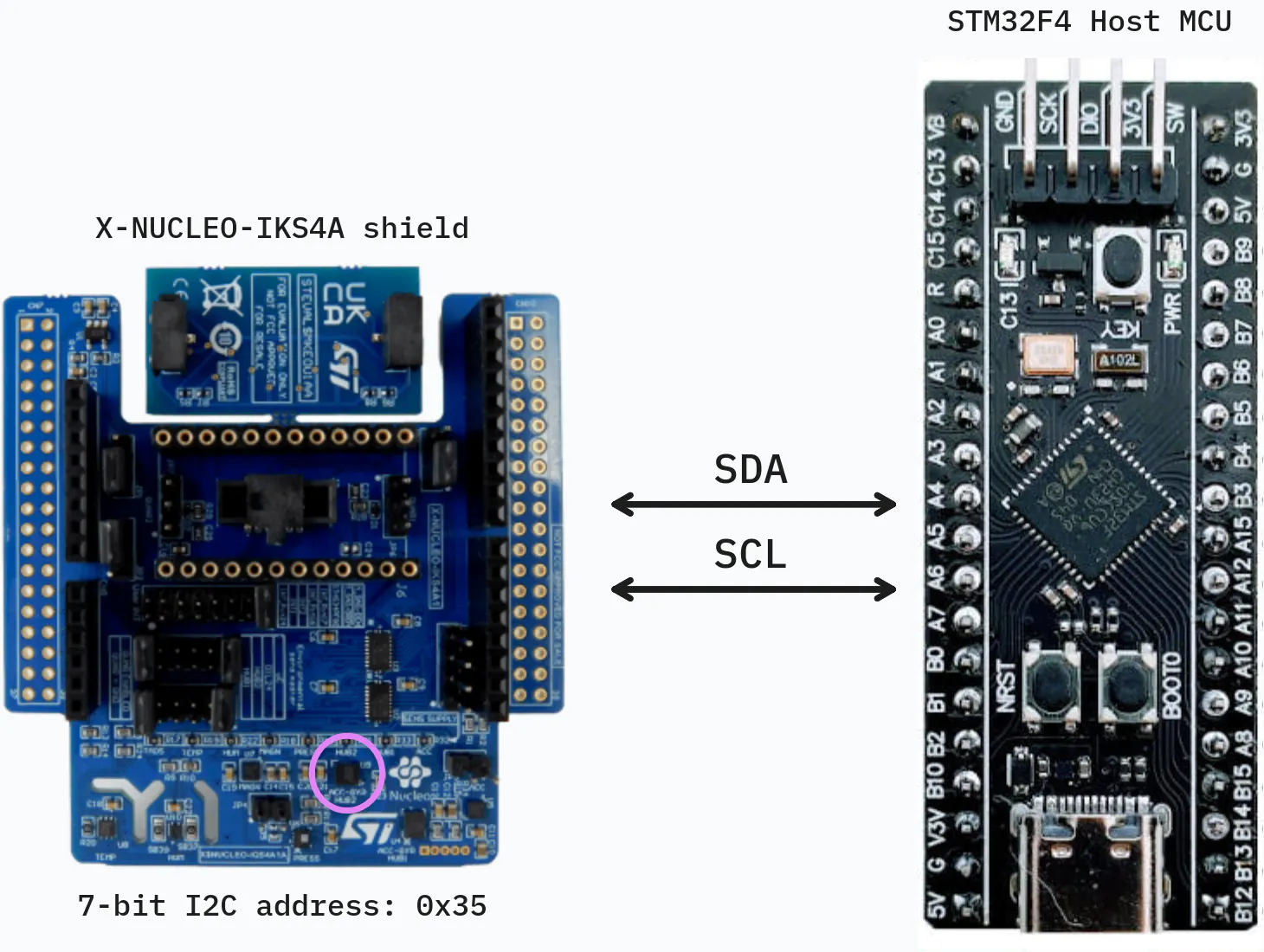
Hardware Architecture. Our system is built around the X-NUCLEO-IKS4A expansion shield. At the heart of this setup is the LSM6DSO16IS, an advanced IMU equipped with an embedded ISPU, which is highlighted in purple in the system diagram. The IMU interfaces with the STM32 host microcontroller via an I2C connection. We utilize the I2C protocol because its low-pin-count serial bus is highly reliable and ideal for power-constrained sensor applications. By using this specific shield and microcontroller combination, we establish a robust foundation for rapid prototyping while allowing the STM32 host to act as a central coordinator. The host MCU is designed to remain in a low-power sleep state, waking only when the IMU explicitly flags an event over the I2C bus.
Dataset. we utilize the UCI Human Activity Recognition (HAR) dataset (link). Using a standardized public dataset ensures our methodology is easily reproducible. The UCI-HAR dataset is based on recordings from 30 volunteers (ages 19–48) performing six standard activities: Walking (0), Walking Upstairs (1), Walking Downstairs (2), Sitting (3), Standing (4), and Laying (5). Here are some properties of the selected dataset:
- 3-axial linear acceleration and 3-axial angular velocity were captured at a constant 50Hz.
- The raw sensor signals were passed through noise filters and separated into body acceleration and gravity using a Butterworth low-pass filter (0.3 Hz cutoff).
- The data was sampled into fixed-width sliding windows of 2.56 seconds with a 50% overlap.
Proposed solution. Instead of continuously streaming this raw data to the host MCU—which drains power rapidly—we implement a power-efficient, two-tier processing pipeline:
- Edge Processing (IMU): The LSM6DSO16IS IMU continuously monitors the user's movements and runs a lightweight, primary classification model. This model differentiates between the broader, simpler activities: Sitting, Standing, Laying, and Walking.
- Deep Analysis (Host MCU): If the IMU determines the current activity is Walking, it triggers an interrupt to wake up the STM32 host MCU. The MCU, which possesses higher processing capabilities, then runs a secondary, more complex model to distinguish between the specific walking sub-classes: Level Walking, Walking Upstairs, and Walking Downstairs.
ISPU Model. We need a microscopic model to fit inside the sensor itself. We first resamples the raw data to 26 Hz, computes basic statistical features, and trains a compact Fully Connected Network. Note that we merges the three distinct walking sub-classes into a single general "Walking" target, producing our four lightweight base classes.
To keep the model footprint tiny and minimize math cycles on the sensor, we rely on a highly optimized handcrafted feature extraction routine:
def compute_window_features(signal_data: Dict[str, np.ndarray]) -> np.ndarray:
    """Build fixed-size handcrafted features per signal and per window."""
    feature_list = []
    for signal_name in SIGNALS:
        values = signal_data[signal_name]
        feature_list.append(values.mean(axis=1))
        feature_list.append(values.std(axis=1))
        feature_list.append(values.var(axis=1))
        feature_list.append(np.sqrt(np.mean(values**2, axis=1)))  # RMS
        feature_list.append(mean_crossing_rate(values))
    return np.stack(feature_list, axis=1).astype(np.float32)
STM32 Host Model. Next, let's train the "big brain" model. We filters the dataset to focus only on the walking sub-classes. Because the host MCU has superior compute capabilities, we train a lightweight 2D Convolutional Neural Network directly on the raw signal windows.
This setup allows the network to automatically capture intricate spatial and temporal patterns across the accelerometer and gyroscope axes:
def build_model(input_shape: Tuple[int, int, int], n_classes: int) -> tf.keras.Model:
    """Create the requested CNN model for raw HAR windows."""
    model = tf.keras.Sequential([
        tf.keras.layers.Input(shape=input_shape),
        tf.keras.layers.Conv2D(filters=24, kernel_size=(16, 1), padding="valid"),
        tf.keras.layers.Activation("relu"),
        tf.keras.layers.MaxPooling2D(pool_size=(3, 1), strides=(3, 1), padding="valid"),
        tf.keras.layers.Flatten(),
        tf.keras.layers.Dense(12),
        tf.keras.layers.Dropout(0.3),
        tf.keras.layers.Dense(n_classes),
    ])
    model.compile(optimizer='adam', loss='sparse_categorical_crossentropy', metrics=['accuracy'])
    return model
Quantization. Microcontrollers don't have gigabytes of RAM. To make our models fit tightly into embedded Flash and RAM, we convert them into optimized TensorFlow Lite (.tflite) formats.
We use INT8 / INT16 post-training quantization, which maps complex floating-point math down to highly efficient integers. This specific configuration preserves model accuracy while drastically cutting down the memory footprint:
# Create TFLite converter
converter = tf.lite.TFLiteConverter.from_keras_model(model)
converter.optimizations = [tf.lite.Optimize.DEFAULT]
converter.representative_dataset = partial(get_representative_data, x_train)

# Allow 16-bit activations and 8-bit weights for peak balance of accuracy and size
converter.target_spec.supported_ops = [
    tf.lite.OpsSet.EXPERIMENTAL_TFLITE_BUILTINS_ACTIVATIONS_INT16_WEIGHTS_INT8
]

tflite_model_quant = converter.convert()Running model on ISPU:
To deploy the AI model on ISPU, we used ST's Toolchain together with MEMS Studio.
Since the ISPU is a resource-constrained embedded processing unit, it cannot run heavy AI runtime libraries or interpreters such as TensorFlow Lite. Therefore, instead of loading the model through an external runtime, the model must be converted and compiled into firmware that can execute directly on the ISPU.
Model Converter - MEMS Studio
As a result, the software tool generated the neccessary source files and configuration files required to implement the motion detection application on ISPU.
The generated files provide the required APIs for initializing and running the model on ISPU. The main APIs used in this project are shown as below:
/* Runtime initializtion */
stai_return_code stai_runtime_init(void);

/* Network initialization */
stai_return_code stai_network_init(stai_network* network);

/* Input and Output buffers initialization */
init_network_buffers(net, input_buffers, output_buffers);

/* Running inference */
stai_return_code stai_network_run(stai_network* network, const stai_run_mode mode)
In this project, the model provides four motion outputs: WALKING, STANDING, SITTING and LYING. To allow these values to be read by externel device such as the Nucleo board, they must be written to the ISPU output registers. The Nucleo board can then read them via the I2C interface for later processing.
cast_float(ISPU_DOUT_00) = out[0]; // Walking score
cast_float(ISPU_DOUT_02) = out[1]; // Sitting score
cast_float(ISPU_DOUT_04) = out[2]; // Standing score
cast_float(ISPU_DOUT_06) = out[3]; // Lying scores
To notify the STM32F401RE that new processed data is available, the ISPU interrupt should be enabled. In this project, the INT1 signal of the LSM6DSO16IS is used and routed to STM32F401RE through the Arduino Connector CN8 pin 6.
In ISPU side, the INT1 is enable in "conf.txt" file (in X-CUBE-ISPU template):
ispu_irq_rate 12.5
ispu_int1 enable
ispu_sleep_int2 enable
ispu_latch disable
The interrupt will be triggered after finishing the inference:
void __attribute__ ((signal)) algo_00(void)
{
    /* Inference processing */
    ...

    /* Generate interrupt on INT1 */
    int_status = int_status | 0x1u;
}
ISPU Runtime Main Loop:
int main(void)
{
    /* set boot done flag */
    uint8_t status = cast_uint8_t(ISPU_STATUS);
    status = status | 0x04u;
    cast_uint8_t(ISPU_STATUS) = status;

    /* enable algorithms interrupt request generation */
    cast_uint8_t(ISPU_GLB_CALL_EN) = 0x01u;

    while (true) {
        stop_and_wait_start_pulse;

        /* reset status registers and interrupts */
        int_status = 0u;
        cast_uint32_t(ISPU_INT_STATUS) = 0u;
        cast_uint8_t(ISPU_INT_PIN) = 0u;

        /* get all the algorithms to run in this time slot */
        cast_uint32_t(ISPU_CALL_EN) = cast_uint32_t(ISPU_ALGO) << 1;

        /* wait for all algorithms execution */
        while (cast_uint32_t(ISPU_CALL_EN) != 0u) {
        }

        /* get interrupt flags */
        uint8_t int_pin = 0u;
        int_pin |= ((int_status & cast_uint32_t(ISPU_INT1_CTRL)) > 0u) ? 0x01u : 0x00u;
        int_pin |= ((int_status & cast_uint32_t(ISPU_INT2_CTRL)) > 0u) ? 0x02u : 0x00u;

        /* set status registers and generate interrupts */
        cast_uint32_t(ISPU_INT_STATUS) = int_status;
        cast_uint8_t(ISPU_INT_PIN) = int_pin;
    }
}
ST's ISPU Toolchain
ST also provides examples and templates to support firmware development on the ISPU. The generated model is then can be integrated into the application as an algorithm and run by ISPU. To build the final firmware for deployment, ST's ISPU Toolchain is required.
The Toolchain can be downloaded and configured in STM32CubeIDE following the instructions provided in ST's X-CUBE-ISPU Github repository: https://github.com/STMicroelectronics/x-cube-ispu/tree/main/Ispu
ST provides instruction videos showing how to use Unicleo-GUI Utility to load program from .ucf file through a Nucleo board. However, the ISPU toolchain can also generate a .h file containing firmware datas. This header file can be included in the STM32 firmware and used to load the ISPU program via I2C connection on on the Nucleo board, which is the approach used in this project.
The built ispu.h file can be then copied to STM32F401RE project. The function to load the ISPU firmware onto IKS4A1 board can be implemented as shown in the following code:
void LSM6DSO16IS_Load_ISPU(I2C_HandleTypeDef *hi2c)
{
    for (uint32_t i = 0; i < (sizeof(ispu_conf_0) / sizeof(ispu_conf_0[0])); i++){
        if (ispu_conf_0[i].type == MEMS_CONF_OP_TYPE_WRITE)
        {
            uint8_t reg  = ispu_conf_0[i].address;
            uint8_t data = ispu_conf_0[i].data;
            (void)HAL_I2C_Mem_Write(hi2c,
                                    LSM6DSO16IS_ADDR,
                                    reg,
                                    I2C_MEMADD_SIZE_8BIT,
                                    &data,
                                    1,
                                    100);
        }
        else if (ispu_conf_0[i].type == MEMS_CONF_OP_TYPE_DELAY)
        {
            HAL_Delay(ispu_conf_0[i].data);
        }
    }
}As with the ISPU deployment, the AI model running on NUCLEO board must be first converted before it can run on the Nucleo F401RE board.
However, in this case, MEMS Studio is intended for MEMS devices and ISPU-based deployment, so it is not suitable for this target. Instead, STM32Cube.AI Studio was used to analyze the model and generate the corresponding embedded AI code for the STM32 microcontroller.
The generated library also provides functions for running model in main program on the Nucleo STM32F401RE. The customized functions used in this project are shown as below:
void STM32CubeAI_Studio_AI_Init(void)
{
    /* USER CODE BEGIN 5 */
    aiInit();
    /* USER CODE END 5 */
}

int acquire_and_process_data(const float *input, uint32_t len) {
    /* Fill the inputs of the c-model */
    if (stai_input[0] == NULL) {
        return -1;
    }

    /* Check if input has enough samples */
    if (len != 78u) {
        return -2;
    }

    memcpy(stai_input[0], input, len * sizeof(float));
    return 0;
}

int post_process(float *output, uint32_t len)
{
    /* process the predictions */
    if (stai_output[0] == NULL) {
        return -1;
    }

    /*
    * New model outputs = 3 class:
    * walking, walking_upstairs, walking_downstairs
    */
    if (len != 3u) {
        return -2;
    }

    memcpy(output, stai_output[0], len * sizeof(float));
    return 0;
}

int aiRun() {
    stai_return_code ret_code;
    /* Perform the inference */
    ret_code = stai_network_run(network_context, STAI_MODE_SYNC);
    if (ret_code != STAI_SUCCESS) {
        ret_code = stai_network_get_error(network_context);
        /* Handle error */
    };
    return 0;
}
Read ISPU Inference Results
The inference results generated by the ISPU can be read using the following function:
HAL_StatusTypeDef LSM6DSO16IS_ReadActivityScores(I2C_HandleTypeDef *hi2c,
float scores[5])
{
    HAL_StatusTypeDef ret;
    uint8_t val;
    uint8_t raw[16];

    /* Enable ISPU interaction register page */
    val = ISPU_REG_ACCESS;
    ret = HAL_I2C_Mem_Write(hi2c, LSM6DSO16IS_ADDR, FUNC_CFG_ACCESS,
                            I2C_MEMADD_SIZE_8BIT, &val, 1, 100);
    if (ret != HAL_OK) return ret;

    /* Read 4 outputs: DOUT_00, DOUT_02, DOUT_04, DOUT_06, DOUT_08 */
    ret = HAL_I2C_Mem_Read( hi2c, LSM6DSO16IS_ADDR, ISPU_DOUT_00_L_REG,
                            I2C_MEMADD_SIZE_8BIT, raw, sizeof(raw), 100);
    /* Restore main page */
    val = 0x00;
    (void)HAL_I2C_Mem_Write(hi2c, LSM6DSO16IS_ADDR, FUNC_CFG_ACCESS,
                            I2C_MEMADD_SIZE_8BIT, &val, 1, 100);

    if (ret != HAL_OK) return ret;

    for (uint8_t i = 0; i < 4; i++)
    {
        memcpy(&scores[i], &raw[i * 4u], sizeof(float));
    }

    return HAL_OK;
}
Interrupt Handling
To enable data processing code the STM32F401RE, a callback function should be used to handle the interrupt generated by the ISPU. In this project, the ISPU INT1 signal is connected to GPIOC pin 0 on the Nucleo board. Therefore, this pin must be configured as an external interrupt input and used to trigger interrtupt handling routine.
The GPIOC pin 0 can be configured in STM32CubeMX, as a result, the code can be seen as below:
/*Configure GPIO pins : PC0 */
GPIO_InitStruct.Pin = GPIO_PIN_0;
GPIO_InitStruct.Mode = GPIO_MODE_IT_RISING;
GPIO_InitStruct.Pull = GPIO_NOPULL;
HAL_GPIO_Init(GPIOC, &GPIO_InitStruct);

/* EXTI interrupt init*/
HAL_NVIC_SetPriority(EXTI0_IRQn, 0, 0);
HAL_NVIC_EnableIRQ(EXTI0_IRQn);
GPIO External Interrupt Callback function:
void HAL_GPIO_EXTI_Callback(uint16_t GPIO_Pin)
{
    if (GPIO_Pin == GPIO_PIN_0)
    {
        ispu_int_detected = 1;
        HAL_GPIO_TogglePin(GPIOA, GPIO_PIN_5);
    }
}
For debugging, GPIOA pin 5, which is connected to the onboard LD2 LED, can be used to check whether the interrupt has been received.
To evaluate the classification result, the STM32 Nucleo board can transmit the output messages via UART2. These messages can be displayed on a serial terminal program such as PuTTY. The example below shows the ISPU classification results together with the host-side model output:
ISPU Model
Performance:
Confusion Matrix:
            walking,sitting,standing,laying
walking     [1387    0    0    0]
sitting     [   0  365   92   34]
standing    [   1   24  491   16]
laying      [   0   43   48  446]

Classification report
precision       recall    f1-score    support
walking         0.9993      1.0000    0.9996      1387
sitting         0.8449      0.7434    0.7909      491
standing        0.7781      0.9229    0.8444      532
laying          0.8992      0.8305    0.8635      537
accuracy                              0.9125      2947
macro avg       0.8804      0.8742    0.8746      2947
weighted avg    0.9154      0.9125    0.9120      2947
Efficiency:
- MAC: 4292
- Inference speed of 1 sample: 9.357 ms
- ROM usage: 16.39 KiB
- RAM usag: 384 B
STM32 Host Model
Performance:
Confusion Matrix:
                    walking,walking_upstairs,walking_downstairs
walking             [484   1  11]
walking_upstairs    [ 36 410  25]
walking_downstairs  [ 17  32 371]]

                        precision    recall  f1-score   support
walking                 0.9013    0.9758    0.9371       496
walking_upstairs        0.9255    0.8705    0.8972       471
walking_downstairs      0.9115    0.8833    0.8972       420
accuracy                                    0.9120      1387
macro avg               0.9128    0.9099    0.9105      1387
weighted avg            0.9126    0.9120    0.9115      1387
Efficiency:
- MAC: 16929
- Inference speed: 5.312 ms
- ROM usage: 16.64 KiB
- RAM usage: 3.74 Ki
Running Models on ISPU and STM32:
The models was successfully deployed and executed on both the ISPU and the STM32F401RE. The system was able to distinguish between dynamic activities, such as walking, and static activities, such as standing, sitting, or lying. However, the classification accuracy between static activities was not always reliable. In particular, standing, sitting and lying were sometimes difficult to seperate from each other.
This limitation is mainly caused by the difference between the real accelerometer input collected from the hardware and the original input data used in the HAR dataset. The sensor placement, sampling condition, orientation, and real-time noise may differ from the dataset used during model training. As a result, the model can still produce meaningful outputs, but the exact classification result may not always be perfectly accurate.
Nevertheless, the main objective of this project to demonstrate the deployment and execution of AI models on both the LSM6DSO16IS ISPU and the STM32F401RE. From this perspective, the project successfully shows inference can be performed on both processing targets and that the results can be read, compared, and displayed. Therefore, the focus of the project is not only on achieving perfect classification accuracy, but also on proving the feasibility of runnig embedded AI on both the sensor-side ISPU abd the host MCU.


Comments