

We built an interactive LED and buzzer system using the STM32F407ZGT6-based RT-Spark Development Board. The goal of the project was to control GPIO pins, read inputs from four buttons, and use Embedded C to light the Red and Yellow LEDs based on the binary value of the button presses. Each button press also played a short Christmas-themed tone. Depending on the input, the LEDs showed Yellow, Red, or both at the same time, which appeared as Orange.
This project responded to different button combinations to play specific songs and control the lights. It showed how digital inputs (buttons) can be used to trigger advanced digital outputs such as sound and LED patterns.
The system used four directional buttons (Left, Right, Up, and Down) as inputs. It produced the following outputs: sound through the buzzer and lights through the Red and Yellow LEDs. • Red Mode was activated and played “Rudolph the Red-Nosed Reindeer” and turned on the Red LED.• Yellow Mode was triggered and it played “Deck the Halls” and turned on the Yellow LED.• Orange light was also produced and played “Jingle Bells.”
The buzzer worked by generating tones manually. The code created sound by switching the buzzer pin on and off at a specific frequency. For example, the note Middle C was produced by toggling the pin at 262 Hz. Each song was made from a sequence of notes, each with its own frequency and duration.
We tested every LED pattern and buzzer output to make sure they worked correctly. Through this process, we improved our understanding of STM32 microcontrollers, digital input and output, simple logic processing, and basic sound generation.
Step 1: Getting StartedWe launched STM32CubeIDE and created a new project. From the Start menu, we selected “New STM32 Project” and chose STM32F407ZGT6 microcontroller. After that, we specified the project name and location, then completed the setup.
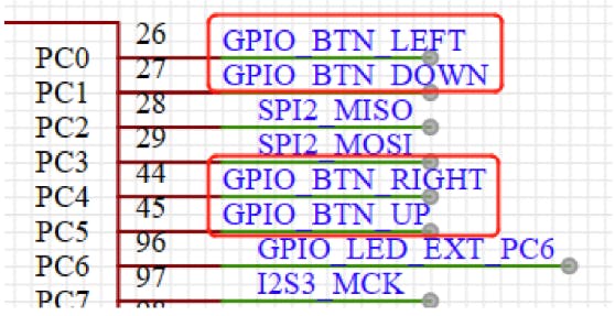
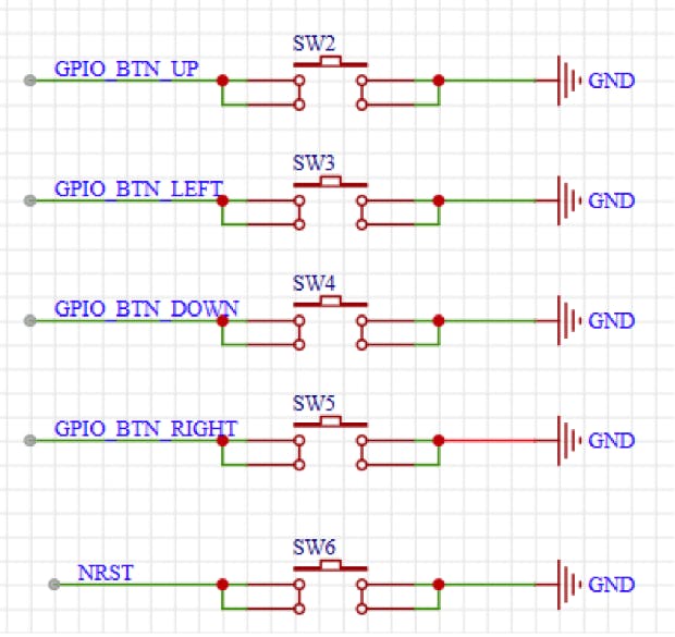
Step 2: Configuring GPIO PinsIn STM32CubeIDE, we opened the Pinout & Configuration section. Using RT-Spark Schematic diagram, the setup of the pins are as follows:
Buttons (Inputs):
- PC0 → Left
- PC1 → Down
- PC4 → Right
- PC5 → Up
LEDS (Outputs):
- PF12 → Red
- PF11 → Yellow
Buzzer:
- PB0 → Buzzer
Now, we navigated to the Core directory in the Project Explorer and opened main.c. From there, we setup our Christmas Digital I/O code.
Step 4: Build and DebugWe connected the RT-Spark board to the laptop using a USB Type-C cable. We built the project using the hammer icon (Ctrl+B). After a successful build, we programmed the board by clicking the Debug (Play) button.
Step 5: Verifying LED PatternsOnce the code was flashed, we observed the LED patterns and sound outputs. Using a reference table, we checked that each button combination produced the correct colors which are Yellow, Red, or Orange and that the buzzer played the correct melody (documentation video here).
After uploading the program, we tested the system and observe the response. The Red and Yellow LEDs lit according to the binary value of the button inputs, while the buzzer played the corresponding Christmas-themed tone for each press. Together, we confirmed that all LED combinations and buzzer outputs worked as intended, enhancing our understanding of digital I/O handling and embedded systems programming.


Comments