

Hardware components | ||||||
 |
| × | 4 | |||
| × | 1 | ||||
 |
| × | 4 | |||
 |
| × | 2 | |||
 |
| × | 1 | |||
Software apps and online services | ||||||
| ||||||
| ||||||
H-Bridge Simulator is an interactive software used to visualize the operation of an H-Bridge circuit, a circuit of four switches (usually transistors) that allows a DC motor to rotate in two directions by controlling the input logic. The simulator displays the direction of current flow, switch status, and motor condition based on the inputs provided, and often includes fault detection features such as short circuits and PWM simulation for speed control. With this tool, users can safely learn and test motor control systems without having to build physical circuits, making it very useful in learning electronics, digital logic, and robotics applications.
1.
The `delay_ms(uint32_t ms)` code is a delay function used to delay program execution for a certain amount of time in milliseconds. This function uses the *SysTick* timer, which is part of the STM32F4 core system. First, the function sets the `SysTick->LOAD` register to a value of 16000 - 1 to produce a delay of 1 ms, assuming a system clock frequency of 16 MHz. Next, `SysTick->VAL` is reset to zero to start the calculation over again. The `SysTick->CTRL` register is set to a value of 5 to enable SysTick with the system clock source without using an interrupt. The function then runs a loop as many times as the value of `ms`, and on each iteration, the program waits until the 16th bit of the `SysTick->CTRL` register becomes 1, which indicates that the timer has reached zero, or one millisecond has passed. After the entire delay process is complete, SysTick is disabled by setting `SysTick->CTRL` to zero.
2.
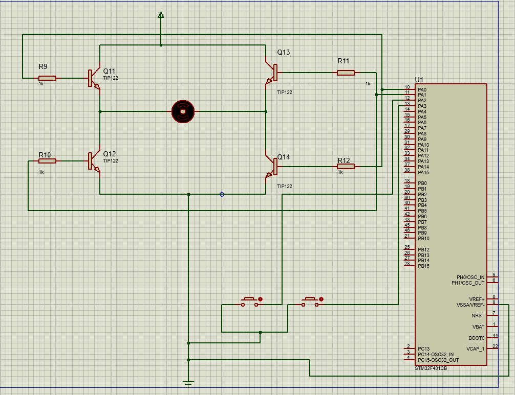
The function of the GPIO_PWM_Init() code is to initialize the PA0 and PA1 pins as PWM outputs using the TIM2 timer. This process is carried out in several steps. First, the clock for GPIOA and TIM2 is activated by setting the RCC->AHB1ENR and RCC->APB1ENR registers. Next, the PA0 and PA1 pins are configured to Alternate Function mode through the MODER register. After that, the AF1 alternative function is selected for both pins, where PA0 is used as the PWM output from the TIM2_CH1 channel for the forward motor direction, and PA1 as the output from TIM2_CH2 for the reverse direction. The purpose of this initialization is so that PA0 and PA1 can be used as PWM outputs to control the direction of motor rotation through the TIM2 timer.
3.
The TIM2_PWM_Init() function is used to initialize Timer 2 on the STM32 microcontroller to generate a 100 Hz PWM signal on channels 1 and 2. The prescaler is set to 159 to lower the clock frequency to 100 kHz, then the ARR is set to 999 to generate a PWM signal with a period of 10 ms (100 Hz).
Both channels are configured in PWM Mode 1 with preload active, allowing fine adjustment of the duty cycle. The initial values of CCR1 and CCR2 are set to 0%, resulting in a LOW output on both channels. The timer is then activated to start generating signals.
This PWM is commonly used to control DC motors, where CH1 can be directed to move forward and CH2 to move backward, depending on the given duty cycle.
4.
In this program section, it functions to set PA2 and PA3 as digital inputs used to read the button status. And activate the internal pull-up resistor so that the pin logic is HIGH (logic 1) when the button is not pressed and the logic becomes LOW (logic 0) when pressed.
In the first program code GPIOA->MODER &= ~((3 << (2 * 2)) | (3 << (3 * 2))); is used to set PA2 and PA3 to Input Mode where MODER is the pin mode configuration register. In the second part of the program code GPIOA->PUPDR &= ~((3 << (2 * 2)) | (3 << (3 * 2))); where PUPDR sets the pull-up / pull-down resistor for each pin. And in the third part of the program code
GPIOA->PUPDR |= (1 << (2 * 2)) | (1 << (3 * 2)); to activate the internal pull-up resistors where PA2 and PA3 are set to pull-up when the button is not pressed, the pin logic is HIGH
5.
This program begins with the initialization of the PWM pin, the input pin for the button, and Timer 2 as the PWM signal generator. After initialization, the program enters an infinite loop to read the buttons continuously.
The first button is connected to pin A2 and the second button to pin A3. The system uses active low logic, so the button is considered active when pressed.
The program logic consists of four conditions. If both buttons are pressed simultaneously, the motor stops. If only the first button is pressed, the motor moves forward at a speed of 70%. If only the second button is pressed, the motor moves backward at a speed of 70%. If no buttons are pressed, the motor remains stopped.
The program provides a 50 millisecond delay per cycle to reduce button bounce. Thus, the motor can be controlled simply and stably with only two buttons.
- Truth Table of H-Bridge Simulator


_3u05Tpwasz.png?auto=compress%2Cformat&w=40&h=40&fit=fillmax&bg=fff&dpr=2)
Comments