


Hardware components | ||||||
 |
| × | 1 | |||
| × | 1 | ||||
| × | 1 | ||||
 |
| × | 1 | |||
| × | 1 | ||||
| × | 1 | ||||
Software apps and online services | ||||||
 |
| |||||
Hand tools and fabrication machines | ||||||
 |
| |||||
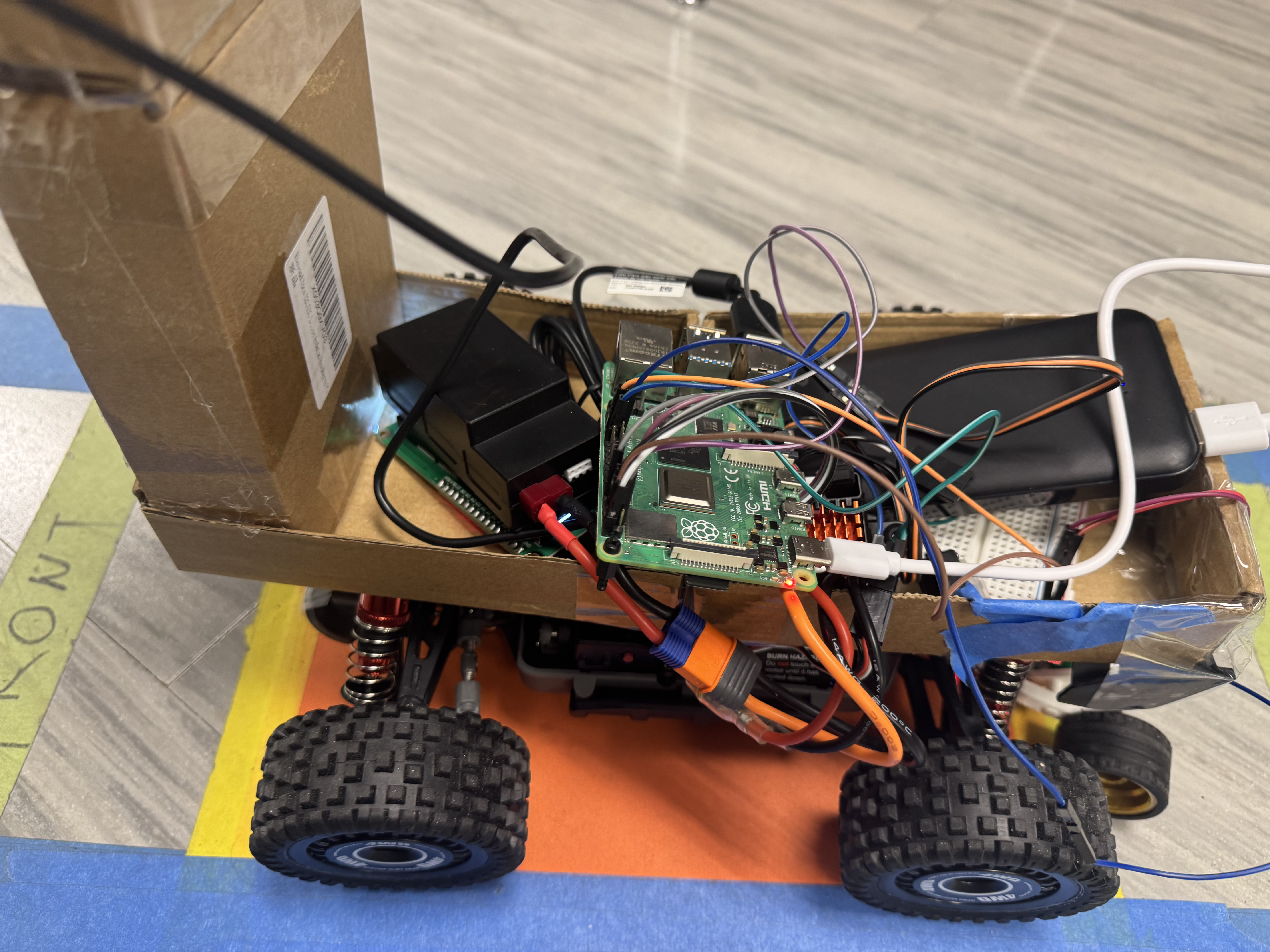
Our autonomous RC car navigates blue-taped lanes using OpenCV for computer vision and a PD controller for smooth steering while dynamically adjusting speed via an optical encoder. Designed for ELEC 424, the project combines hardware resilience and software precision to handle real-world track conditions.
Tuning the Vision & Control System:Determining the optimal camera resolution (160x120) involved balancing processing speed and lane-detection accuracy—too high caused lag, too low lost critical details. For control, we tested multiple PD gains, settling on kp = 0.09 (proportional) and kd = 0.045 (derivative, half of kp) after observing overshoot with higher values. The encoder’s feedback range (5M–8.5M ns/tick) was calibrated by logging wheel rotation times at different PWM speeds.
Stop Detection: From Theory to Reliable Practice:Red stop-sign detection initially struggled with false positives until we implemented dual HSV masking (0–10° and 170–180°) and a 28% pixel threshold. Hardware debouncing in the encoder driver (1ms delay) and a two-stage stop-check system (waiting 100 frames after the first sign) eliminated erratic stops. Collaboration with TAs and other teams revealed ambient light affected detection—solving this required tuning HSV bounds dynamically during testing.
The Power of Teamwork & Adaptability:When our first motor driver failed, rapid prototyping with spare parts (guided by the professor) kept us on schedule. Debugging I/O conflicts in the encoder driver—via sysfs checks and TA advice—taught us kernel-module troubleshooting. By studying teams ahead of us, we incorporated their guidance on the DTS overlay structure and bash script necessary to insert the needed modules, proving that collaboration accelerates innovation.
Citations:Raja_961: https://www.instructables.com/Autonomous-Lane-Keeping-Car-Using-Raspberry-Pi-and/
Team Colonel Hackers: https://www.hackster.io/colonel-hackers/autonomous-rc-car-elec-424-final-project-732fd1
Team ReaLly BaD Idea: https://www.hackster.io/really-bad-idea/autonomous-path-following-car-6c4992
Team Paul Walker: https://www.hackster.io/paul-walker/autonomous-rc-car-eebfb4?f=1
Team M.E.G.G.: https://www.hackster.io/m-e-g-g/the-magnificent-m-e-g-g-car-28ec89


# Team: Ulises Moreno, John David Villarreal, Devin Gonzalez, Liam Waite
# Class: ELEC 424
# Final Project
# Spring 2025
#
#
# Code derived from:
# https://www.hackster.io/colonel-hackers/autonomous-rc-car-elec-424-final-project-732fd1
# https://www.hackster.io/really-bad-idea/autonomous-path-following-car-6c4992
# https://www.hackster.io/paul-walker/autonomous-rc-car-eebfb4?f=1
import cv2
import numpy as np
import math
import time
import RPi.GPIO as GPIO
import matplotlib.pyplot as plt
import os
import sys
#import board
#import busio
#import adafruit_mcp4728
### Initialize GPIO ###
# Set GPIO mode
GPIO.setmode(GPIO.BCM)
# Pin configs
GPIO.setup(18, GPIO.OUT) #Initializes GPIO 18 as OUTPUT
GPIO.setup(19, GPIO.OUT) #Initializes GPIO 19 as OUTPUT
freq = 50 #Frequency of PWM signal
# Initialize PWM for ESC and servo
pwm_esc = GPIO.PWM(18, freq) #creates a PWM at GPIO 18 running at 50Hz
pwm_serv = GPIO.PWM(19, freq) #creates a PWM at GPIO 19 running at 50Hz
### Inits ###
# Start PWM signals
pwm_esc.start(7.5) #puts DC motor on neutral
pwm_serv.start(7.5) #sets servo motor straight
# Manage car behaviour
speed_encode = True
encoder_path = "/sys/module/gpiod_driver/parameters/encoder_val"
#encoder_path = "/sys/module/gpiod_driver_encoder/parameters/encoder_val"
encoder_max_rotation = 5000000 # max speed
encoder_min_rotation = 8500000 # min speed
# PD control constants
kp = 0.09 # proportional gain
kd = kp*0.5 # derivative gain
# Speed control parameters
zero_speed = 7.5 # car is stopped
base_speed = 8.35 # car moves forward slowly
speed_change = 0.001
zero_turn = 7.5 # neutral steering
# Track encoder readings
global_enc_vals = []
# Limit on loop cycles
max_ticks = 4000
cam_idx = 0 # camera index
### Functions ###
# Custom exception for permission error
class NotSudo(Exception):
pass
# Reset car to default position and speed
def reset_car():
pwm_esc.ChangeDutyCycle(7.5) #puts DC motor on neutral
pwm_serv.ChangeDutyCycle(7.5) #servo straight
# Start car with base speed and straight steering
def start_car():
print("Car ready")
pwm_esc.ChangeDutyCycle(base_speed) #puts DC motor on neutral
pwm_serv.ChangeDutyCycle(7.5) #servo straight
# Dynamically adjust car speed using encoder feedback
def manage_speed():
f = open(encoder_path, "r")
enc = int(f.readline()) #value from encoder
f.close()
ret = enc
global_enc_vals.append(enc)
print("this is enc:")
print(enc)
ret = 0 #no speed change
# Check if speed is too high or too low
if enc <= encoder_max_rotation: #too fast
ret = -(speed_change * 0.01) #reduce speed
elif enc >= encoder_min_rotation: #too slow
ret = (speed_change * 0.01) #increase speed
return ret
# Delay execution for a specified time
def wait(wait_time):
start_time = time.perf_counter() # start
end_time = start_time + wait_time # end
while (time.perf_counter() < end_time):
pass
return
# Detect blue edges in the camera frame
def detect_edges(frame):
hsv = cv2.cvtColor(frame, cv2.COLOR_BGR2HSV)
lower_blue = np.array([90, 50, 50], dtype="uint8")
upper_blue = np.array([130, 255, 255], dtype="uint8")
mask = cv2.inRange(hsv, lower_blue, upper_blue)
edges = cv2.Canny(mask, 50, 100)
return edges
# Crop image to only include lower half of frame
def region_of_interest(edges):
height, width = edges.shape
mask = np.zeros_like(edges)
polygon = np.array([[
(0, height),
(0, height / 2),
(width, height / 2),
(width, height),
]], np.int32)
cv2.fillPoly(mask, polygon, 255)
cropped_edges = cv2.bitwise_and(edges, mask)
return cropped_edges
# Use Hough Transform to find lines
def detect_line_segments(cropped_edges):
rho = 1
theta = np.pi / 180
min_threshold = 10
line_segments = cv2.HoughLinesP(cropped_edges, rho, theta, min_threshold,
np.array([]), minLineLength=5, maxLineGap=150)
return line_segments
def average_slope_intercept(frame, line_segments):
lane_lines = []
if line_segments is None:
print("No line segments detected")
return lane_lines
height, width, _ = frame.shape
left_fit = []
right_fit = []
boundary = 1 / 3
left_region_boundary = width * (1 - boundary)
right_region_boundary = width * boundary
for line_segment in line_segments:
for x1, y1, x2, y2 in line_segment:
if x1 == x2:
continue
fit = np.polyfit((x1, x2), (y1, y2), 1)
slope = (y2 - y1) / (x2 - x1)
intercept = y1 - (slope * x1)
if slope < 0:
if x1 < left_region_boundary and x2 < left_region_boundary:
left_fit.append((slope, intercept))
else:
if x1 > right_region_boundary and x2 > right_region_boundary:
right_fit.append((slope, intercept))
# Take average of left and right lines
left_fit_average = np.average(left_fit, axis=0)
if len(left_fit) > 0:
lane_lines.append(make_points(frame, left_fit_average))
right_fit_average = np.average(right_fit, axis=0)
if len(right_fit) > 0:
lane_lines.append(make_points(frame, right_fit_average))
return lane_lines
# Convert slope and intercept to pixel points
def make_points(frame, line):
height, width, _ = frame.shape
slope, intercept = line
y1 = height
y2 = int(y1 / 2)
if slope == 0:
slope = 0.1
x1 = int((y1 - intercept) / slope)
x2 = int((y2 - intercept) / slope)
return [[x1, y1, x2, y2]]
# Overlay detected lines on frame
def display_lines(frame, lines, line_color=(0, 255, 0), line_width=6):
line_image = np.zeros_like(frame)
if lines is not None:
for line in lines:
for x1, y1, x2, y2 in line:
cv2.line(line_image, (x1, y1), (x2, y2), line_color, line_width)
line_image = cv2.addWeighted(frame, 0.8, line_image, 1, 1)
return line_image
# Draw a line showing the steering direction
def display_heading_line(frame, steering_angle, line_color=(0, 0, 255), line_width=5):
heading_image = np.zeros_like(frame)
height, width, _ = frame.shape
steering_angle_radian = steering_angle / 180.0 * math.pi
x1 = int(width / 2)
y1 = height
x2 = int(x1 - height / 2 / math.tan(steering_angle_radian))
y2 = int(height / 2)
cv2.line(heading_image, (x1, y1), (x2, y2), line_color, line_width)
heading_image = cv2.addWeighted(frame, 0.8, heading_image, 1, 1)
return heading_image
# Compute steering angle based on lane lines
def get_steering_angle(frame, lane_lines):
height, width, _ = frame.shape
if len(lane_lines) == 2:
_, _, left_x2, _ = lane_lines[0][0]
_, _, right_x2, _ = lane_lines[1][0]
mid = int(width / 2)
x_offset = (left_x2 + right_x2) / 2 - mid
y_offset = int(height / 2)
elif len(lane_lines) == 1:
x1, _, x2, _ = lane_lines[0][0]
x_offset = x2 - x1
y_offset = int(height / 2)
elif len(lane_lines) == 0:
x_offset = 0
y_offset = int(height / 2)
angle_to_mid_radian = math.atan(x_offset / y_offset)
angle_to_mid_deg = int(angle_to_mid_radian * 180.0 / math.pi)
steering_angle = angle_to_mid_deg + 93
return steering_angle
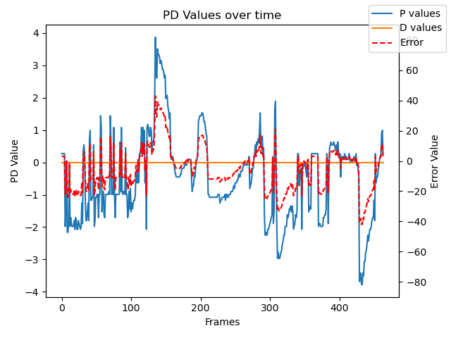
# Plot proportional, derivative values and error
def plot_pd(p_vals, d_vals, error, show_img=False):
fig, ax1 = plt.subplots()
t_ax = np.arange(len(p_vals))
ax1.plot(t_ax, p_vals, '-', label="P values")
ax1.plot(t_ax, d_vals, '-', label="D values")
ax2 = ax1.twinx()
ax2.plot(t_ax, error, '--r', label="Error")
ax1.set_xlabel("Frames")
ax1.set_ylabel("PD Value")
ax2.set_ylim(-90, 90)
ax2.set_ylabel("Error Value")
plt.title("PD Values over time")
fig.legend()
fig.tight_layout()
plt.savefig("pd_plot.png")
if show_img:
plt.show()
plt.clf()
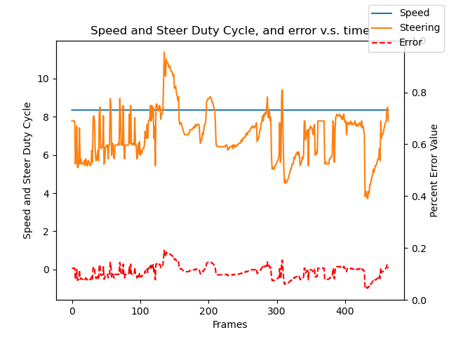
# Plot PWM values and normalized error
def plot_pwm(speed_pwms, turn_pwms, error, show_img=False):
fig, ax1 = plt.subplots()
t_ax = np.arange(len(speed_pwms))
ax1.plot(t_ax, speed_pwms, '-', label="Speed")
ax1.plot(t_ax, turn_pwms, '-', label="Steering")
ax2 = ax1.twinx()
ax1.plot(t_ax, error / np.max(error), '--r', label="Error")
ax1.set_xlabel("Frames")
ax1.set_ylabel("Speed and Steer Duty Cycle")
ax2.set_ylabel("Percent Error Value")
plt.title("Speed and Steer Duty Cycle, and error v.s. time")
fig.legend()
plt.savefig("voltage_plot.png")
if show_img:
plt.show()
plt.clf()
# adapted from hackster, changed to adhere to red HSV color segments
def isRedFloorVisible(image):
"""
Detects whether or not the majority of a color on the screen is a particular color
:param image:
:param boundaries: [[color boundaries], [success boundaries]]
:return: boolean if image satisfies provided boundaries, and an image used for debugging
"""
# Convert to HSV color space
hsv_img = cv2.cvtColor(image, cv2.COLOR_BGR2HSV)
cv2.imwrite("redfloor.jpg", hsv_img)
# Set the percentage threshold for color detection
percentage = 28
# lower and upper range for the lower part of red
lower_red1 = np.array([0, 40, 60], dtype="uint8")
upper_red1 = np.array([10, 255, 255], dtype="uint8")
# lower and upper range for the upper part of red
lower_red2 = np.array([170, 40, 60], dtype="uint8")
upper_red2 = np.array([180, 255, 255], dtype="uint8")
# create two masks to capture both ranges of red
mask1 = cv2.inRange(hsv_img, lower_red1, upper_red1)
mask2 = cv2.inRange(hsv_img, lower_red2, upper_red2)
# combine the masks
mask = cv2.bitwise_or(mask1, mask2)
# apply the mask to original image
output = cv2.bitwise_and(hsv_img, hsv_img, mask=mask)
# save the masked image
cv2.imwrite("redfloormask.jpg", output)
# calculate the percentage of red detected
percentage_detected = np.count_nonzero(mask) * 100 / np.size(mask)
# return true if threshold is surpassed
result = percentage < percentage_detected
if result:
print(percentage_detected)
return result, output
### Main Loop ###
def main():
# Setup timing and control variables
lastTime = 0
lastError = 0
SecondStopTick = 0
# Arrays for plotting PD and control data
p_vals = [] # proportional
d_vals = [] # derivative
err_vals_1 = [] # error
err_vals_2 = [] # error
speed_vals = [] # speed values
steer_vals = [] # steering values
# Set up video capture
video = cv2.VideoCapture(cam_idx)
video.set(cv2.CAP_PROP_FRAME_WIDTH, 320)
video.set(cv2.CAP_PROP_FRAME_HEIGHT, 240)
# Start the car
start_car()
curr_speed = base_speed
counter = 0
passedFirstStopSign = False
# Main control loop
while counter < max_ticks:
print("beginning of measurement")
pwm_esc.ChangeDutyCycle(zero_speed)
# Read a frame from the camera
ret, original_frame = video.read()
frame = cv2.resize(original_frame, (160, 120))
# Process image to detect lane lines
edges = detect_edges(frame)
cv2.imshow("edges", edges)
roi = region_of_interest(edges)
line_segments = detect_line_segments(roi)
# Get lane lines from segments
lane_lines = average_slope_intercept(frame, line_segments)
lane_lines_image = display_lines(frame, lane_lines)
# Determine steering angle from lane lines
steering_angle = get_steering_angle(frame, lane_lines)
heading_image = display_heading_line(lane_lines_image, steering_angle)
# Compute time since last loop and error from center
now = time.time()
dt = now - lastTime
deviation = steering_angle - 90
# PD controller calculations
error = deviation
base_turn = 7.505
proportional = kp * error
derivative = kd * (error - lastError) / dt
# Record values for plotting
p_vals.append(proportional)
d_vals.append(derivative)
err_vals_1.append(error)
speed_vals.append(curr_speed)
# Compute new turn amount from PD values
turn_amt = base_turn + proportional + derivative
steer_vals.append(turn_amt)
# Apply steering adjustment
pwm_serv.ChangeDutyCycle(turn_amt)
# Stop at red floor (stop sign) detection
if counter % 20:
if not passedFirstStopSign:
isStopSign, floorSight = isRedFloorVisible(frame)
if isStopSign:
wait(3)
passedFirstStopSign = True
SecondStopTick = counter
# Handle second stop
elif passedFirstStopSign and counter > SecondStopTick + 100:
isStopSign, _ = isRedFloorVisible(frame)
if isStopSign:
pwm_esc.ChangeDutyCycle(zero_speed)
print("Reached final stop")
break
# Speed regulation with encoder feedback
if speed_encode:
if counter % 3 == 0:
temp_speed = manage_speed() + curr_speed
print("this is temp_speed")
print(temp_speed)
if temp_speed != curr_speed:
pwm_esc.ChangeDutyCycle(temp_speed)
curr_speed = temp_speed
# Maintain speed and delay before next loop
pwm_esc.ChangeDutyCycle(curr_speed)
print("current pwm:")
print(curr_speed)
wait(0.023)
# Exit on ESC key
key = cv2.waitKey(1)
if key == 27:
break
counter += 1
# Clean up
reset_car()
video.release()
cv2.destroyAllWindows()
# Generate and save plots
plot_pd(p_vals, d_vals, err_vals_1)
print("dimensions")
print(speed_vals)
print(steer_vals)
print(err_vals_1)
plot_pwm(speed_vals, steer_vals, err_vals_1)
if __name__ == "__main__":
main()
#include <linux/module.h>              // Core header for loading LKMs into the kernel
#include <linux/of_device.h>          // For device tree matching
#include <linux/kernel.h>             // Contains types, macros, functions for the kernel
#include <linux/timekeeping.h>        // For getting kernel time
#include <linux/ktime.h>              // For high-resolution timestamps
#include <linux/moduleparam.h>        // For module parameters
#include <linux/hrtimer.h>            // High-resolution timers
#include <linux/interrupt.h>          // For IRQ handling
#include <linux/of.h>                 // Device tree parsing
#include <linux/gpio/consumer.h>      // GPIO consumer API
#include <linux/platform_device.h>    // Platform driver definitions
#include <linux/interrupt.h>          // (duplicated include) For IRQ macros/functions


/**
 * Code from:  Haochen(Jason) Zhang, Ye Zhou, Konstantinos Alexopoulos
 * Class: COMP 424 ELEC 424/553 001
 * Final Project: Autonomous Car
 * Fall 2023
 *
 * Interrupt code derived from:
 * https://github.com/Johannes4Linux/Linux_Driver_Tutorial/blob/main/11_gpio_irq/gpio_irq.c
 */

// Global variables
unsigned int irq_number;                      // IRQ number assigned to encoder GPIO
static struct gpio_desc *my_enc;              // GPIO descriptor for encoder pin
static volatile u64 prev_time;                // Timestamp of previous interrupt
static volatile u64 curr_time;                // Timestamp of current interrupt

static int encoder_val;                       // Exposed variable for measured time between encoder ticks
module_param(encoder_val, int, 0644);         // Make encoder_val readable/writable from sysfs

// Interrupt handler for encoder pin
static irq_handler_t gpio_irq_handler(unsigned int irq, void *dev_id, struct pt_regs *regs) {

	// Read current value of encoder GPIO (should be 1 on rising edge)
	int enc_val = gpiod_get_value(my_enc);

	// Get current high-resolution time
	curr_time = ktime_get_ns();
	unsigned long elapsed_time = curr_time - prev_time;

	// If rising edge and debounce threshold is satisfied (>1 ms)
	if (enc_val == 1 && elapsed_time > 1000000) {
		prev_time = curr_time;                 // Update last known interrupt time
		encoder_val = elapsed_time;            // Store elapsed time globally
		printk(KERN_INFO "irq_handler - timing detected: %lu", elapsed_time);
	}

	return (irq_handler_t) IRQ_HANDLED;        // Notify kernel interrupt has been handled
}


// Probe function called when the device is matched via device tree
static int enc_probe(struct platform_device *pdev)
{
	struct device *dev;
	dev = &pdev->dev;                         // Get pointer to device struct

	printk("enc_probe - RUNNING v5\n");

	// Request GPIO descriptor for encoder using label "encoder"
	my_enc = gpiod_get(dev, "encoder", GPIOD_IN);
	if(IS_ERR(my_enc)) {
		printk("enc_probe - could not gpiod_get for encoder\n");
		return -1;
	}

	// Convert GPIO descriptor to IRQ number
	irq_number = gpiod_to_irq(my_enc);

	// Set debounce interval to 1 ms (1,000,000 ns)
	gpiod_set_debounce(my_enc, 1000000);

	// Request IRQ for rising edge triggers on encoder GPIO
	if(request_irq(irq_number, (irq_handler_t) gpio_irq_handler, IRQF_TRIGGER_RISING, "my_gpio_irq", NULL) != 0){
		printk("Error!\nCannot request interrupt nr.: %d\n", irq_number);
		return -1;
	}

	// Initialize previous time for first interrupt measurement
	prev_time = ktime_get_ns();

	printk("enc_probe - SUCCESS\n");
	return 0;
}

// Cleanup function when the driver is removed
static void enc_remove(struct platform_device *pdev)
{
	// Free IRQ associated with encoder GPIO
	free_irq(irq_number, NULL);
	printk("enc_remove - Freed interrupt & Removing\n");
	return;
}

// Device tree match table used to bind platform driver to device
static struct of_device_id matchy_match[] = {
    { .compatible = "a_second_name", },       // Must match device tree "compatible" property
	{},
};

// Platform driver structure
static struct platform_driver my_driver = {
	.probe	 = enc_probe,                     // Called on device detection
	.remove	 = enc_remove,                   // Called on device removal
	.driver	 = {
	       .name  = "The Rock: this name doesn't even matter", // Kernel-internal name
	       .owner = THIS_MODULE,             // Indicates this module owns the driver
	       .of_match_table = matchy_match,   // Device tree match table
	},
};

// Register platform driver
module_platform_driver(my_driver);

// Module metadata
MODULE_ALIAS("platform:my_driver");
MODULE_DESCRIPTION("424's finest");
MODULE_AUTHOR("UlisesM, LiamW, DevinG, JohnDavidV");
MODULE_LICENSE("GPL v2");


Comments