

Hardware components | ||||||
| × | 1 | ||||
Software apps and online services | ||||||
 |
| |||||
 |
| |||||
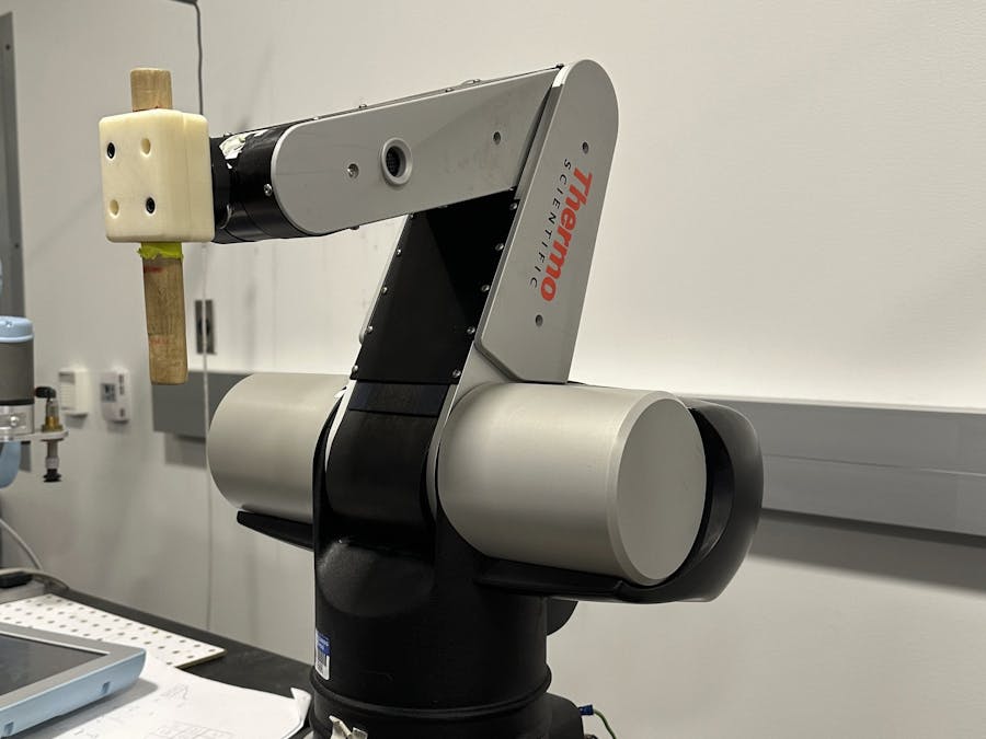
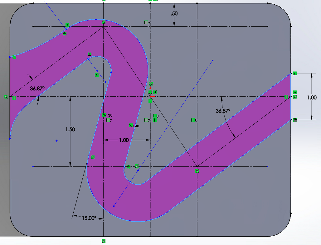
The objective of this project is to control the provided CRS robotic arm to perform a series of tasks in its workspace. Specifically, the robotic arm is expected to insert its end-effector tool into a peg hole for half of a second, navigate through a zig-zag maze, and press down on an egg with a weight of approximately 500-1000 grams.
SetupTo accomplish this, a series of positional coordinates (x, y, z) were recorded and stored in the robot as waypoints. Each waypoint had a corresponding time value, which describes how long it should take the robot to move to this waypoint from the previous waypoint. Additionally, the desired force application and directional gains were stored.
TrajectoryDuring the main procedure, the robot loops through a series of waypoints. First, the robot records the angles of each of its three joints and stores this information for later use. Next, it calculates the desired position of the end-effector at the current time step using a linear function derived from the goal waypoint and previous waypoint. It also calculates the desired velocity, by taking the derivative of this linear function. Finally, the robot checks if it has reached the current goal waypoint and if the desired amount of time has passed. If both of these conditions are met, the goal waypoint is incremented.
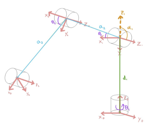
Forward KinematicsThe forward kinematics function is used to calculate the position of the end effector in xyz coordinates based on the current joint angles. This is accomplished by utilizing the Denavit-Hartenberg method.
Task Space ControlOnce the desired end-effector position and velocity are found, the actual joint velocity is calculated using the derivative approximation. All of these values are passed into a task-space PD controller, which calculates what torques the motors should be applying. The torque values are split up into three components, all of which are summed together for each individual joint. To determine the first component, it uses this actual velocity to create friction compensation offsets, which are used to overcome the inherent friction in the robot. The second component comes from the task-space equation, which determines the main driving torque required to minimize the positional and velocity errors. This is done by multiplying the error by a coefficient that determines how strong of a correcting torque the robot should provide. The final component is calculated using the desired force the robot should apply on the environment. The desired force is specified by the waypoints created during setup. This force is normally zero except when applying a force directly to the egg. Once these three components are summed together for each joint, the values are saturated to prevent damage to the robot or its surroundings.

#include "math.h"
#include "F28335Serial.h"

#define PI          3.1415926535897932384626433832795
#define TWOPI       6.283185307179586476925286766559
#define HALFPI      1.5707963267948966192313216916398
#define GRAV        9.81

// These two offsets are only used in the main file user_CRSRobot.c  You just need to create them here and find the correct offset and then these offset will adjust the encoder readings
// ========================================================= //
// Offset values used to match the motor angle zero with the DH angle zero
float offset_Enc2_rad = -.452;
float offset_Enc3_rad = .242;
// ========================================================= //

// Your global varialbes.

long mycount = 0;

#pragma DATA_SECTION(whattoprint, ".my_vars")
float whattoprint = 0.0;

#pragma DATA_SECTION(theta1array, ".my_arrs")
float theta1array[100];
float theta2array[100];

// ========================================================= //
// global variables defining the DH and motor angles of the joints
/* contains the theta values in DH terms calculated by the inverse kinematics function*/
float theta1_IK_DH;
float theta2_IK_DH;
float theta3_IK_DH;
/* contains the motor theta values calculated by the inverse kinematics function*/
float theta1_IK_motor = 0.0;
float theta2_IK_motor = 0.0;
float theta3_IK_motor = 0.0;
/* contains the angles at which the impedence control frame are rotated about*/
float thetax = 0.0;
float thetay = 0.0;
float thetaz = 0.0;
// The following values are for the PIecewise PID control
/* Kpx, Kpy, and Kpz are the proportional gains used in the PID control*/
float Kpx = 800.0;
float Kpy = 800.0;
float Kpz = 600.0;
/* Kdx, Kdy, and Kdz are the derivative gains used in the PID control*/
float Kdx = 20.0;
float Kdy = 20.0;
float Kdz = 15.0;
/* Kff is the friction compensation gain. Kt is the robot's torque constant*/
float Kff = .6;
float Kt = 6.0;
// global variables defining the friction values
float u_fric1 = 0;
float u_fric2 = 0;
float u_fric3 = 0;
float Visc_pos_1 = 0.2513;
float Visc_neg_1 = 0.2477;
float Coul_pos_1 = 0.3637;
float Coul_neg_1 = -0.2948;
float Visc_pos_2 = 0.25;
float Visc_neg_2 = 0.2870;
float Coul_pos_2 = 0.4759;
float Coul_neg_2 = -0.5031;
float Visc_pos_3 = 0.1922;
float Visc_neg_3 = 0.5339;
float Coul_pos_3 = 0.2132;
float Coul_neg_3 = -0.519;
float v_min_1 = 0.1;
float v_min_2 = 0.05;
float v_min_3 = 0.05;
float Stat_1 = 3.6;
float Stat_2 = 3.6;
float Stat_3 = 3.6;

/* Initialization of the initial and previous position and theta values*/
float prev_position[3] = {0, 0, 0};
float prev_theta[3] = {0, 0, 0};
bool isFirstLoop = true;

float position_des[3] = {0, 0, 0};
float velocities_des[3] = {0, 0, 0};

float position_1[3] = {.35, .127, .508};
float position_2[3] = {.35, -.127, .254};
float linearSpeed = .08;
float t_start = 0;
float t_total = 0;
// ========================================================= //
long arrayindex = 0;
int UARTprint = 0;

// ========================================================= //
// global variable for the end-effector homogeneous transformation matrix
float H[4][4];
float x_actual;
float y_actual;
float z_actual;
// ========================================================= //
float printtheta1motor = 0;
float printtheta2motor = 0;
float printtheta3motor = 0;

// Assign these float to the values you would like to plot in Simulink
float Simulink_PlotVar1 = 0;
float Simulink_PlotVar2 = 0;
float Simulink_PlotVar3 = 0;
float Simulink_PlotVar4 = 0;

// ========================================================= //
// Used to test the interaction between Code Composer Studio, Matlab, and Simulink
// Not used for further calculations
float random_variable = 1239087.32;
// ========================================================= //

// Structure defining the desired position, force, Kp gains, and time to complete waypoint step
typedef struct {
    float x_des;
    float y_des;
    float z_des;
    float z_force;
    float T_diff;
    float Kpx;
    float Kpy;
    float Kpz;
} Waypoint;

// current step, total number of steps, and list of the desired waypoints
int curr_step = 0;
const int num_steps = 24;
Waypoint waypoints[num_steps] = {{0.254,0,0.508,0,2, 800.0, 800.0, 600.0}, //first random linear move
                        {0.0344,0.3444,0.253,0,2, 800.0, 800.0, 600.0}, //above peg
                        {0.0344,0.3444,0.253,0,1, 800.0, 800.0, 600.0}, // wait 1 second
                        {0.0344,0.3444,0.1396,0,3, 400.0, 400.0, 600.0}, //in peg
                        {0.0344,0.3444,0.1396,0,1, 400.0, 400.0, 600.0}, // wait 1 second
                        {0.0344,0.3444,0.253,0,2, 400.0, 400.0, 600.0}, // out of peg
                        {0.257,0.111,0.209,0,2, 800.0, 800.0, 600.0}, // intermediate
                        {0.373,0.111,0.209,0,2, 800.0, 800.0, 600.0}, // entrance of zig zag
                        {0.4085, 0.0604, 0.209, 0, 2, 800.0, 800.0, 600.0}, // start zig zag
                        {0.4091, 0.04989, 0.209, 0, 0.5, 800.0, 800.0, 600.0}, //start curve
                        {0.40362, 0.04155, 0.209, 0, 0.5, 800.0, 800.0, 600.0}, // middle of curve
                        {0.39346, 0.03745, 0.209, 0,0.5, 800.0, 800.0, 600.0}, // end of curve
                        {0.334455,0.05128, 0.209, 0,2, 800.0, 800.0, 600.0}, // straight portion
                        {0.3266, 0.04846, 0.209, 0, 0.5, 800.0, 800.0, 600.0}, // middle curve
                        {0.3183, 0.03794, 0.209, 0, 0.5, 800.0, 800.0, 600.0}, // middle curve
                        {0.3212, 0.02811, 0.209, 0, 0.5, 800.0, 800.0, 600.0}, // end curve
                        {0.38188, -0.049588, 0.209, 0, 3, 800.0, 800.0, 600.0}, // last zig zag pt
                        {0.3955, -0.066, 0.209, 0, 2, 800.0, 800.0, 600.0}, // outside of zig zag
                        {0.255, -0.066, 0.309, 0, 3, 800.0, 800.0, 600.0}, // intermediate
                        {0.261, 0.20118, 0.309, 0, 3, 800.0, 800.0, 600.0}, // above egg
                        {0.261, 0.20118, 0.28711, 6.9, 2, 800.0, 800.0, 0.0}, // push on egg
                        {0.261, 0.20118, 0.28711, 6.9, 2, 800.0, 800.0, 0.0}, // hold on egg
                        {0.261, 0.20118, 0.309, 0, 3, 800.0, 800.0, 600.0}, // above egg
                        {0.254,0,0.508,0,2, 800.0, 800.0, 600.0}}; // end point

/* Initialization of the current and previous waypoints*/
Waypoint curr_waypoint = {0.254,0,0.508,0,2, 800.0, 800.0, 600.0};
Waypoint prev_waypoint = {0.135660142, 0, 0.421622366, 0, 0, 800.0, 800.0, 600.0};
/* Error between the desired and actual end effector position*/
float error = 0;
/* Maximum error before the robot can move to the next waypoint*/
float error_threshold = 0.01;
void mains_code(void);

// ========================================================= //
// Pre-initialization of the kinematic functions
void ForwardKinematic(float motor1, float motor2, float motor3);
void InverseKinematics(float x, float y, float z);
void Trajectory(float t);
void PID(float dest[3], float dot_dest[3], float theta_curr[3], float *tau1, float *tau2, float *tau3);
// Global defining the length between the 2nd joint and the end-effector
// Used in inverse Iknematic solution
float a = 0;
// ========================================================= //

//
// Main
//
void main(void)
{

    mains_code();
}


// This function is called every 1 ms
void lab(float theta1motor,float theta2motor,float theta3motor,float *tau1,float *tau2,float *tau3, int error) {

    /*
        Completes the desired steps for the control of the robot
        Input Args:
            theta1motor : current angle of motor 1  (rad)
            theta2motor : current angle of motor 2  (rad)
            theta3motor : current angle of motor 3  (rad)
            tau1        : pointer to the input torque for joint 1 (Nm)
            tau2        : pointer to the input torque for joint 2 (Nm)
            tau3        : pointer to the input torque for joint 3 (Nm)
            error       : value describing the safety mode of the system
     */

    /*
        This function first calls the forward and inverse kinematic functions. This is not used in this specific lab, however they may prove useful in the future.
        Then, the velocities for each joint are calculated using a derivative approximation. The velocity is averaged with the previous two timesteps, and then the velocity
        values are stored as the previous timesteps.

        The angles and velocities for each joint are stored into arrays and then the PID function is called using said arrays as well as the target thetas and the torques.

        The arrays are stored in an index every 50ms and every 1000ms, the target theta value is changed between 0 and PI/6. Every 500ms, the LED's are flashed.

        Then, the print values and simulink values are both updated for analysis and plotting purposes. The functions by increment the count value.
     */

    // Calls the Forward and Inverse Iknematic functions to solve for the positions and angles
    // Solves for position
    ForwardKinematic(theta1motor, theta2motor, theta3motor);
    // Solves for motor and DH angles
    InverseKinematics(H[0][3], H[1][3], H[2][3]);
    // Defines the velocities of the joints

    /* group the motor angles and motor velocities into arrays for input into the PID function*/
    float theta_current[3] = {theta1motor, theta2motor, theta3motor};

    Trajectory(mycount);
    PID(position_des, velocities_des, theta_current, tau1, tau2, tau3);
    // ========================================================= //

    // *tau1 = 0;
    // *tau2 = 0;
    // *tau3 = 0;

    //Motor torque limitation(Max: 5 Min: -5)

    // save past states
    if ((mycount%50)==0) {

        theta1array[arrayindex] = theta1motor;
        theta2array[arrayindex] = theta2motor;

        if (arrayindex >= 99) {
            arrayindex = 0;
        } else {
            arrayindex++;
        }

    }
    /*
    The Lab function runs every 1ms. Therefore, to create the desired step input with a period of 2 seconds, the goal_thetas will be toggled between 0 and PI/6
    every 1000 counts.
     */


    if ((mycount%500)==0) {
        UARTprint = 1;
        GpioDataRegs.GPBTOGGLE.bit.GPIO34 = 1; // Blink LED on Control Card
        GpioDataRegs.GPBTOGGLE.bit.GPIO60 = 1; // Blink LED on Emergency Stop Box
    }

    printtheta1motor = theta1motor;
    printtheta2motor = theta2motor;
    printtheta3motor = theta3motor;

    /*
    These are the variables are sent to simulink. To effectively tune the PID gains, the motor angles and the desired angles are sent
     */
    Simulink_PlotVar1 = theta1motor;
    Simulink_PlotVar2 = theta2motor;
    Simulink_PlotVar3 = theta3motor;
    Simulink_PlotVar4 = 0;

    mycount++;
}

void printing(void) {
    if (whattoprint == 0) {
        //        serial_printf(&SerialA, "%.2f %.2f,%.2f   \n\r",printtheta1motor*180/PI,printtheta2motor*180/PI,printtheta3motor*180/PI);
        //serial_printf(&SerialA, "%.2f \n\r", random_variable);

        // ========================================================= //
        // Prints the DH, motor, and measured angles (all in degrees) as well as the end-effector position (in cm) to TerraTerm
        serial_printf(&SerialA, "Meas: th1: %.2f, th2: %.2f, th3: %.2f \n\r", printtheta1motor*180/PI, printtheta2motor*180/PI, printtheta3motor*180/PI);
        serial_printf(&SerialA, "x: %.2f, y: %.2f, z: %.2f \n\r", H[0][3], H[1][3], H[2][3]);
        serial_printf(&SerialA, "DH: th1: %.2f, th2: %.2f, th3: %.2f \n\r", theta1_IK_DH*180/PI, theta2_IK_DH*180/PI, theta3_IK_DH*180/PI);
        serial_printf(&SerialA, "Motor: th1: %.2f, th2: %.2f, th3: %.2f \n\r\n\r", theta1_IK_motor*180/PI, theta2_IK_motor*180/PI, theta3_IK_motor*180/PI);
        // ========================================================= //
    } else {
        // ========================================================= //
        // Prints the position of the end-effector. Not used
        serial_printf(&SerialA, "x: %.2f, y: %.2f, z: %.2f \n\r", H[0][3], H[1][3], H[2][3]);
        // ========================================================= //
    }
}

// ========================================================= //
// Takes in three floats defining three joint motor angles. Stores the position information to global variables and returns nothing
void ForwardKinematic(float theta1motor, float theta2motor, float theta3motor) {
    // Initializes a new matrix containing the homogeneous transformation matrix of the end-effector in terms of motor angles
    // The exact equations were first calculated in matlab and coPIed over
    float FK[4][4] = {{cos(theta1motor)*cos(theta3motor), -cos(theta1motor)*sin(theta3motor), -sin(theta1motor),  (127.0*cos(theta1motor)*(cos(theta3motor) + sin(theta2motor)))/500.0},
                      {cos(theta3motor)*sin(theta1motor), -sin(theta1motor)*sin(theta3motor),  cos(theta1motor),  (127.0*sin(theta1motor)*(cos(theta3motor) + sin(theta2motor)))/500.0},
                      {-sin(theta3motor), -cos(theta3motor), 0, (127.0*cos(theta2motor))/500.0 - (127.0*sin(theta3motor))/500.0 + 127.0/500.0},
                      {0, 0, 0, 1}};
    x_actual = FK[0][3];
    y_actual = FK[1][3];
    z_actual = FK[2][3];
    // Loops through the information in the FK homogeneous transformation matrix and stores each cell in the global H HTM
    // Necessary for the matrix to be stored after the function concludes since FK is deleted after the function is completed
    for (int i = 0; i < 4; ++i) {
        for (int j = 0; j < 4; ++j) {
            H[i][j] = FK[i][j];
        }
    }
}
// ========================================================= //


// ========================================================= //
// Takes in three floats defining the x, y, z position of the end-effector. Stores the motor and DH angles to global variables and returns nothing
void InverseKinematics(float x, float y, float z) {
    // Defines projected x-y distance (in cm) between the end-effector and the world frame (zero frame)
    float xE = sqrt(x*x + y*y);
    // Determines the DH angle (in rads) of theta1 using the x-y position of the end-effector
    theta1_IK_DH = atan2(y,x);
    // CoPIes the DH angle (in rads) to the motor angle since they are the same
    theta1_IK_motor = theta1_IK_DH;
    // Calculates the distance (in cm) between joint 2 and the end-effector. Used in future calculations
    a = sqrt(xE*xE + (z - 0.254) * (z - 0.254));
    // Uses Law of Cosines to calculate the DH theta3 angle (in rads). Uses the arm link lengths (in cm) and the "a" distance
    theta3_IK_DH = acos((a*a - 2*0.254*0.254)/(2*0.254*0.254));
    // Uses the Law of Sines to calculate the DH theta2 angle (in rads). Uses theta3, arm link lengths (in cm), and the "a" distance
    theta2_IK_DH = -(asin(0.254*sin(theta3_IK_DH)/a) + asin((z - 0.254)/a));
    // Uses the DH to motor angle conversion equations to get the theta2 motor angle (in rads)
    theta2_IK_motor = theta2_IK_DH + PI/2;
    // Uses the DH to motor angle conversion equations to get the theta3 motor angle (in rads)
    theta3_IK_motor = theta3_IK_DH + theta2_IK_motor - PI/2;
}
// ========================================================= //

void Trajectory(float t) {

    /*
        Determines the desired motor angles at the current time given the trajectory path
        Input Args:
            t : current time (ms)
        Function description:
            This function starts by computing the Euclidean distance between the previous waypoint and the current goal waypoint.
            In the first if block, we check if the time elapsed is less than the desired total time. If it is not, we set the position destination to
            the current goal rather than continuing to use the straight line trajectory
            The straight line trajectory is calculated using the following equation:
                x_d = del_*(t-t_start)/t_total + x_actual
                y_d = del_*(t-t_start)/t_total + y_actual
                z_d = del_*(t-t_start)/t_total + z_actual

            The last step is to determine whether to continue to the next waypoint or not. This is done by calculating the error between the current position and the
            next waypoint. If the error is within a threshold and the time elapsed is greater than the desired total time, then the waypoint is incremented.
            An addtional check is used to prevent the waypoint from incrementing outside of the array of waypoints.
    */
    /* Straight line trajectory */
    t /= 1000;
    float deltaPosition[3] = {curr_waypoint.x_des - prev_waypoint.x_des, curr_waypoint.y_des - prev_waypoint.y_des, curr_waypoint.z_des - prev_waypoint.z_des};

    if (t - t_start < curr_waypoint.T_diff) {

        position_des[0] = deltaPosition[0]*(t - t_start)/curr_waypoint.T_diff + prev_waypoint.x_des;
        position_des[1] = deltaPosition[1]*(t - t_start)/curr_waypoint.T_diff + prev_waypoint.y_des;
        position_des[2] = deltaPosition[2]*(t - t_start)/curr_waypoint.T_diff + prev_waypoint.z_des;
        velocities_des[0] = deltaPosition[0]/curr_waypoint.T_diff;
        velocities_des[1] = deltaPosition[1]/curr_waypoint.T_diff;
        velocities_des[2] = deltaPosition[2]/curr_waypoint.T_diff;
    } else {
        position_des[0] = curr_waypoint.x_des;
        position_des[1] = curr_waypoint.y_des;
        position_des[2] = curr_waypoint.z_des;
        velocities_des[0] = 0;
        velocities_des[1] = 0;
        velocities_des[2] = 0;
    }
    error = sqrt((curr_waypoint.x_des - x_actual)*(curr_waypoint.x_des - x_actual) + (curr_waypoint.y_des - y_actual)*(curr_waypoint.y_des - y_actual) + (curr_waypoint.z_des - z_actual)*(curr_waypoint.z_des - z_actual));
    if ((error < error_threshold) && (t - t_start) >= curr_waypoint.T_diff && (curr_step != (num_steps - 1))) {
        prev_waypoint = curr_waypoint;
        curr_step++;
        curr_waypoint = waypoints[curr_step];
        t_start = t;

    }
}

void PID(float dest[3], float dot_dest[3], float theta_curr[3], float *tau1, float *tau2, float *tau3) {

    /*
        Determines the torques to input to the motors using PID control and/or impedence
        Input Args:
            dest[]          : array of floats containing goal positions of the end effector (m)
            dot_dest[]      : array of floats containing the goal velocities of the end effector (m/s)
            theta_curr[]    : array containing the current position of the motors (rad)
            tau1            : pointer to the input torque for joint 1
            tau2            : pointer to the input torque for joint 2
            tau3            : pointer to the input torque for joint 3
     */

    /* detailed description
        This starts be determining the actual motor velocities using the derivative approximation.
        Next, friction compensation is calculated for each joint and the end effeector position and velocity are found.
        The Kp's are overriden based on the current step's commands, and Task Space PID control is calculated.
        If there is a force being commanded, the Feedforward force is added to the torque and the torque is then saturated between its limits.
        Finally, the current end effector position and motor angles are recorded as the previous values for the next iteration.
     */


    float theta1_dot = (theta_curr[0] - prev_theta[0])/0.001;
    float theta2_dot = (theta_curr[1] - prev_theta[1])/0.001;
    float theta3_dot = (theta_curr[2] - prev_theta[2])/0.001;

    /* Friction compensation */
    /* The following blocks of code are used to calculate the friction compensation coefficients.
    * There are three regions of interest in friction compensation, viscous friction and coulombic friction in the positive and negative directions.
    * Since the torque due to friction as a function of velocity is a step function, very high accelerations would be commanded to the robot if this were modeled.
    * Therefore, the coulombic friction is used to approximate this step input for small angular velocities.
    * Once the velicity passes a threshold, v_min_# in this case, then a viscous friction model is used. In this model, the friction is a linear function of the joint velocity.
    * The following three blocks of code
    */
    if (theta1_dot > v_min_1) {
        u_fric1 = Visc_pos_1*theta1_dot + Coul_pos_1;
    } else if (theta1_dot < -v_min_1) {
        u_fric1 = Visc_neg_1*theta1_dot + Coul_neg_1;
    } else {
        u_fric1 = Stat_1*theta1_dot;
    }

    if (theta2_dot > v_min_2) {
        u_fric2 = Visc_pos_2*theta2_dot + Coul_pos_2;
    } else if (theta2_dot < -v_min_2) {
        u_fric2 = Visc_neg_2*theta2_dot + Coul_neg_2;
    } else {
        u_fric2 = Stat_2*theta2_dot;
    }

    if (theta3_dot > v_min_3) {
        u_fric3 = Visc_pos_3*theta3_dot + Coul_pos_3;
    } else if (theta3_dot < -v_min_3) {
        u_fric3 = Visc_neg_3*theta3_dot + Coul_neg_3;
    } else {
        u_fric3 = Stat_3*theta3_dot;
    }


    float x = H[0][3];
    float y = H[1][3];
    float z = H[2][3];

    float x_dot = (x - prev_position[0])/0.001;
    float y_dot = (y - prev_position[1])/0.001;
    float z_dot = (z - prev_position[2])/0.001;


    if (isFirstLoop) {
        x_dot = 0;
        y_dot = 0;
        z_dot = 0;
        isFirstLoop = false;
    }

    float c_theta_1 = cos(theta_curr[0]);
    float s_theta_1 = sin(theta_curr[0]);
    float c_theta_2 = cos(theta_curr[1]);
    float s_theta_2 = sin(theta_curr[1]);
    float c_theta_3 = cos(theta_curr[2]);
    float s_theta_3 = sin(theta_curr[2]);
    float c_theta_x = cos(thetax);
    float c_theta_y = cos(thetay);
    float c_theta_z = cos(thetaz);
    float s_theta_x = sin(thetax);
    float s_theta_y = sin(thetay);
    float s_theta_z = sin(thetaz);
    Kpx = curr_waypoint.Kpx;
    Kpy = curr_waypoint.Kpy;
    Kpz = curr_waypoint.Kpz;

    /* Task space  PD control*/
     *tau1 = Kff*u_fric1 + (127.0*s_theta_1*(Kpx*(x - dest[0]) + Kdx*(x_dot - dot_dest[0]))*(c_theta_3 + s_theta_2))/500.0 - (127.0*c_theta_1*(Kpy*(y - dest[1]) + Kdy*(y_dot - dot_dest[1]))*(c_theta_3 + s_theta_2))/500.0;
     *tau2 = Kff*u_fric2 + (Kpz*(z - dest[2]) + Kdz*(z_dot - dot_dest[2]))*((127.0*c_theta_3)/500.0 + (127.0*s_theta_2)/500.0) - (127.0*c_theta_1*(Kpx*(x - dest[0]) + Kdx*(x_dot - dot_dest[0]))*(c_theta_2 - s_theta_3))/500.0 - (127.0*s_theta_1*(Kpy*(y - dest[1]) + Kdy*(y_dot - dot_dest[1]))*(c_theta_1 - s_theta_3))/500.0;
     *tau3 = Kff*u_fric3 + (127.0*c_theta_3*(Kpz*(z - dest[2]) + Kdz*(z_dot - dot_dest[2])))/500.0 + (127.0*c_theta_1*s_theta_3*(Kpx*(x - dest[0]) + Kdx*(x_dot - dot_dest[0])))/500.0 + (127.0*s_theta_1*s_theta_3*(Kpy*(y - dest[1]) + Kdy*(y_dot - dot_dest[1])))/500.0;
    /* Adds the feedforward force */
    *tau1 += 0;
    *tau2 -= 0.254*(c_theta_3 + s_theta_2) * curr_waypoint.z_force / Kt;
    *tau3 -= 0.254*c_theta_3 * curr_waypoint.z_force/Kt;
    if (*tau1 > 5) {
        *tau1 = 5;
    } else if (*tau1 < -5) {
        *tau1 = -5;
    }

    if (*tau2 > 5) {
        *tau2 = 5;
    } else if (*tau2 < -5) {
        *tau2 = -5;
    }

    if (*tau3 > 5) {
        *tau3 = 5;
    } else if (*tau3 < -5) {
        *tau3 = -5;
    }


    prev_position[0] = x;
    prev_position[1] = y;
    prev_position[2] = z;

    prev_theta[0] = theta_curr[0];
    prev_theta[1] = theta_curr[1];
    prev_theta[2] = theta_curr[2];

}


Comments