


Hardware components | ||||||
 |
| × | 1 | |||
 |
| × | 1 | |||
| × | 1 | ||||
 |
| × | 1 | |||
| × | 3 | ||||
 |
| × | 1 | |||
 |
| × | 4 | |||
 |
| × | 1 | |||
 |
| × | 1 | |||
Software apps and online services | ||||||
| ||||||
 |
| |||||
Hand tools and fabrication machines | ||||||
 |
| |||||
 |
| |||||
 |
| |||||
Background:
One of the most precious things in my life is sleep. I am a true believer that a quality rest leads to quality in all the other aspects of one’s life. I have found that for myself, I get the best sleep in a cold room with some white noise in the background. The temperature lets me lay fully under the covers, and the white noise source will drown out random background sounds. Fortunately, the Lasko Box Fan exists, allowing me to lower the temperature in my room, or at least around my bed, in addition to providing a wonderful sound that prevents me from hearing the random nighttime chatter of college students or the scraping of moving chairs. This has made the box fan a mainstay in my room for years, both in school and out. Given that I use the device so often, I thought why not take the chance to turn the $20 box fan into a smart device, one that I can control with my phone. Thus begins the story of the EZ Cool 1.0
Inspiration:
I was inspired by a fellow student’s automated lighting system, which was a similar concept of taking a simple operating device and automating it using a motor. The project can be found here:
OperationTo operate the EZ Cool 1.0 device, follow the instructions below:
- Remove the control knob of your Lasko fan, and replace it with the 3D printed knob component.
- Connect the EZ Cool 1.0 device to the 3D printed knob component. (Note: This is a future component of thE EZ Cool device. Currently the knob component is not operational).
- Plug in your EZ Cool 1.0 device to power using the micro USB to USB C cable. Setup is complete once the red LED lights up.
- Use the two buttons on the far side of the device to operate the EZ Cool, power on the fan, and change the speeds.
- In case of emergency, press the red button
Breadboard Setup
This project is entirely based around the PocketBeagle, and thus I first planned how I wanted to be adding my additional components to the PocketBeagle on its breadboard. Fortunately, this project would not need a large number of additional components, so I used a single breadboard with the PocketBeagle on one end.
PocketBeagle
- The PocketBeagle needs to have the headers soldered onto it if not already done; most PocketBeagles do not come ready for usage out of the box
- The PocketBeagle can then be placed on the end of the breadboard, with the head (end with the micro USB port) facing outwards
- The PocketBeagle is then able to be connected to a computer via the outward facing micro USB port
- Breadboard powering
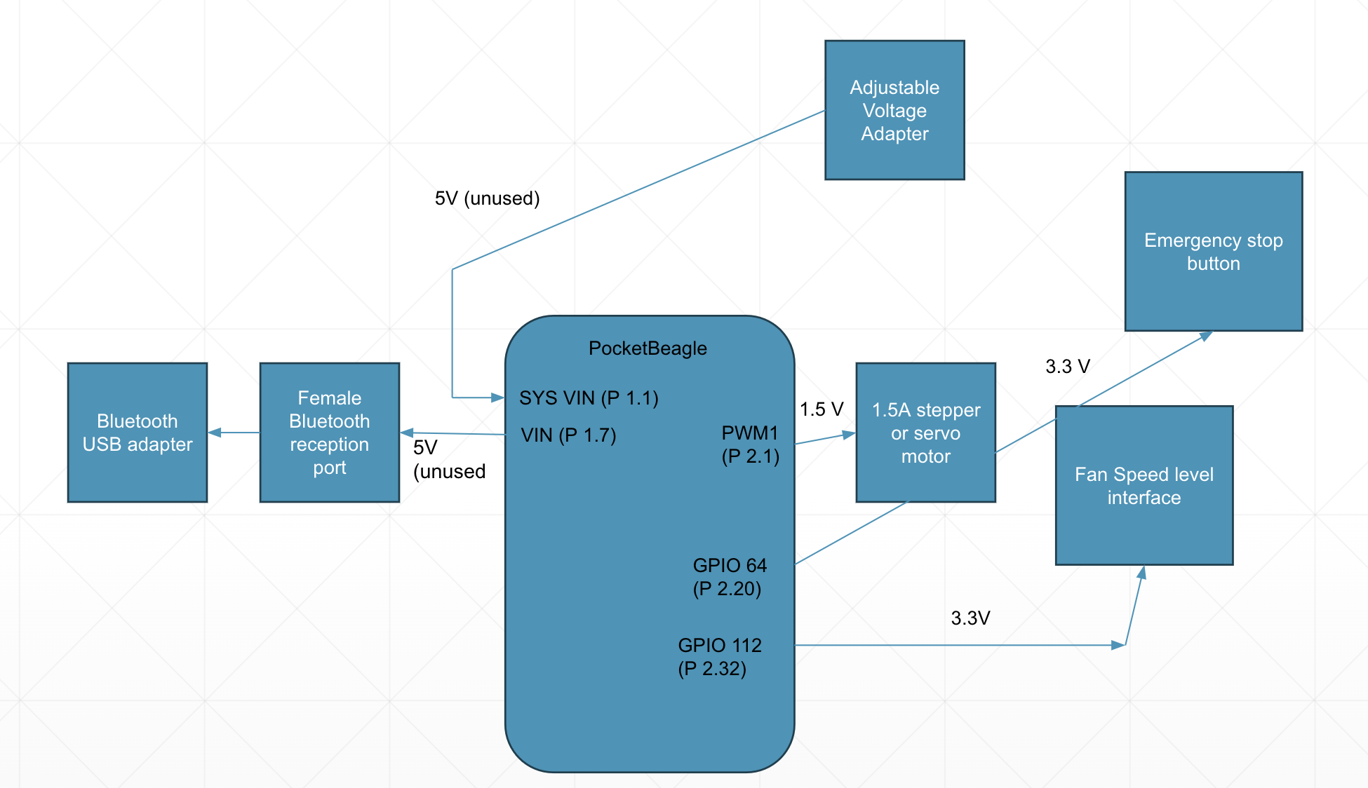
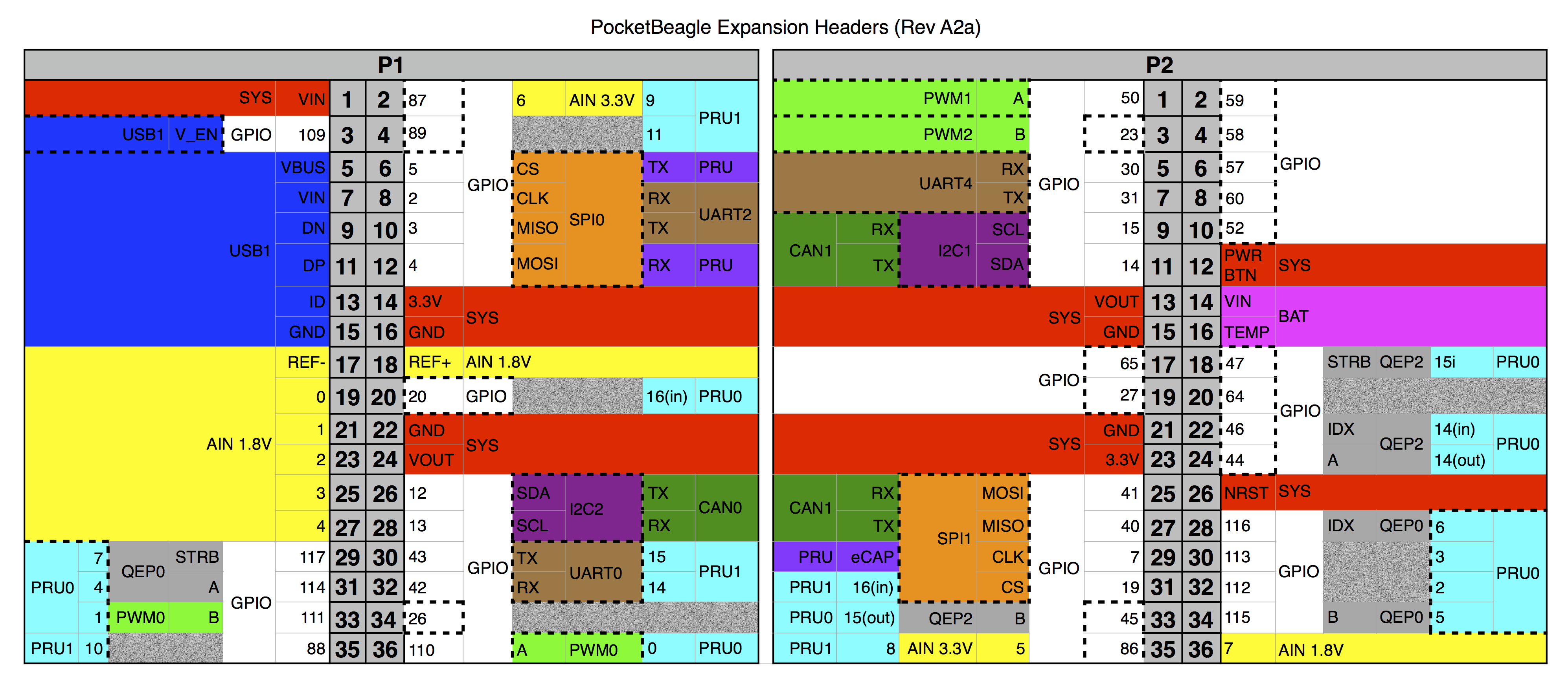
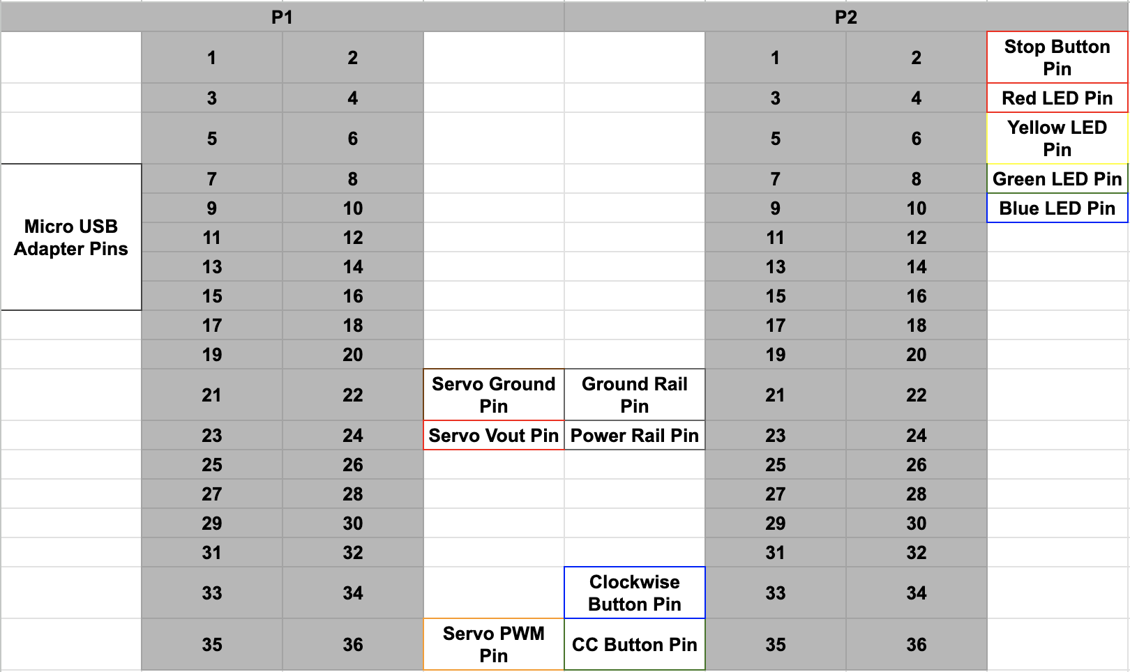
The PocketBeagle and its micro USB port are able to provide the necessary 3.3 volt power supply for the components of the project. One side of the breadboard was used to create power rails for each of the buttons within the device. These rails were created by connecting cables from P2_21 to the - rail for Ground (blue rail) and from P2_23 to the + rail for 3.3V power (red).
This rail also allows for additional connections beyond the scope of this project.
Motor
The SG90 Servo motor is what provides the main function of the project and allows it to interact with the box fan.
- The motor is connected to Ground via the brown wire, leading to P1_22
- The motor is connected to VCC Vout via the red wire, leading to P1_24
- The motor is connected to the PWM pin via the orange wire at P1_36
Unfortunately, this motor provided neither the power nor torque necessary to interact with the box fan knob, an oversight on my part. This project would be complete with the addition of a servo with a higher torque or power.
Buttons
The EZ Cool 1.0 is equipped with 3 buttons that are meant to act as an additional control option, as well as a way to kill the code in case of some kind of malfunction or emergency.
- Place buttons across the middle section of the breadboard. The plastic nubs at the bottom should sit within the middle trough.
- Using the power rails created earlier, add a resistor (1k resistors were used in this project) leading to the + power rail as well as a small wire connection leading to the grounding rail.
- Place each button so that it has connection to power and ground, and place a wire between the button and the resistor leading to the + power rail.
- Each button’s wire can lead to any GPIO pin. In this project, the buttons lead to pins, P2_02, P2_33, and P2_35
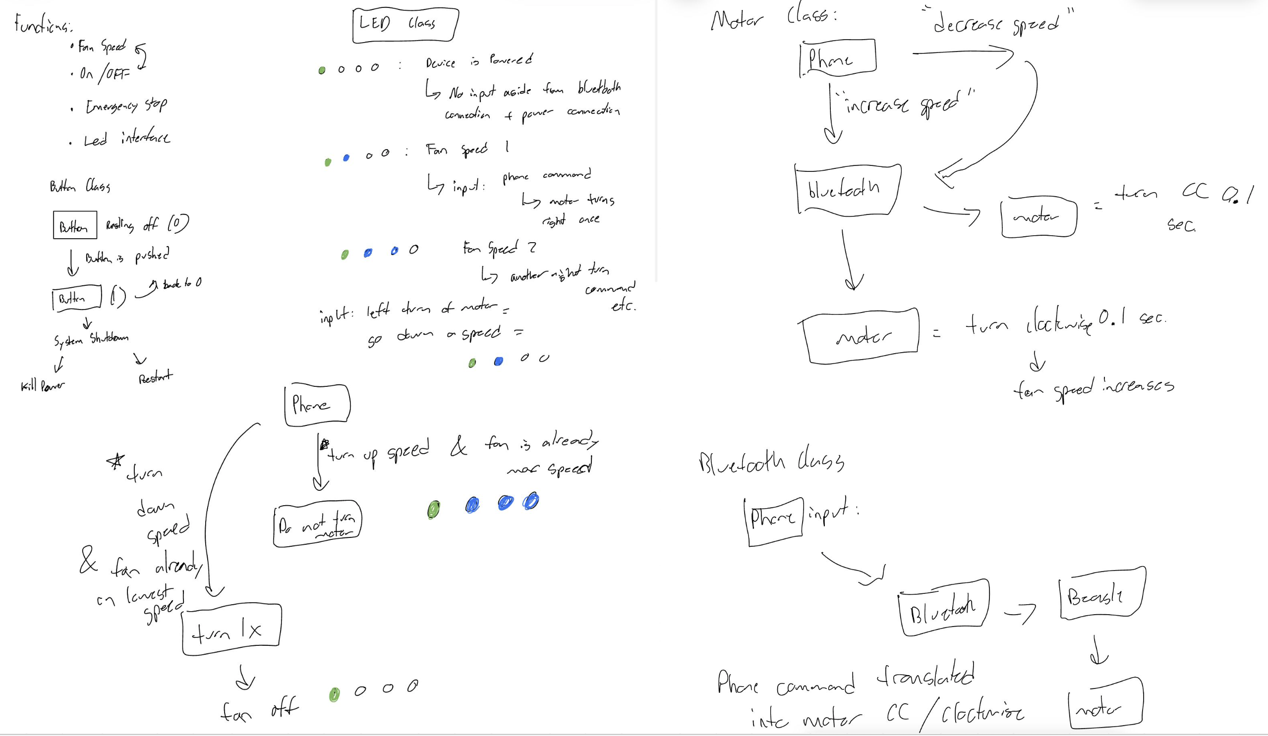
The blue and green buttons allow for control over the SG90 servo motor, pushing them will lead to movement of the fan knob, turning the fan on or off and increasing or decreasing the speed. The current power level is determined by the LEDs, which will be explained shortly.
The red button is separated from the other two, and will kill the code and stop the fan when pressed.
These buttons were meant to be used as a secondary input for fan control, but ended up being the primary input method.
LEDs
The LEDs provide a visual representation of the fan’s current operation. The red LED is always lit while the device is operational, and will be the only LED lit when the fan is not on. As the fan turns on and changes speeds, the yellow, green, and blue lights will light up and turn off incrementally to provide visual aid of the fan’s operation status. For each LED:
- Be careful of the LED’s orientation. The Anode, the long lead of the LED must lead to the PocketBeagle, while the Cathode, the shorter lead, needs to go to ground (in this project, via the - rail)
- Connect each LED to the PocketBeagle using a wire leading from the Anode to any GPIO pin.
- In this project, the pins used for LEDs are P2_04, P2_06, P2_08, and P2_10 on the PocketBeagle.
Bluetooth Adapter
The bluetooth adapter is integrated into the project, but is not utilized. To connect the adapter, use five jumper cables to connect the adapter to pins P1_07, P1_09, P1_11, P1_13, and P1_15 on the PocketBeagle.
Demonstration
Future ConsiderationsUnfortunately some problems were encountered in the development of the device. Initially when given the instructions for the project, my immediate worry was that there would be an intense struggle when it came to coding the project, as I had no prior experience with any form of python, aside from maybe a single week 3 years ago. This worry made programming my focus for a large portion of the time provided for the project. This focus caused me to neglect the actual mechanical portions of the project until it was a bit too late.
There are two main improvements that need to be made to the project:
- Bluetooth/Wifi integration:
The initial proposal for this project included the usage of the bluetooth adapter in order to allow the EZ Cool to connect to bluetooth enabled devices, most specifically cell phones, to allow the user to control the box fan with their phone or another smart device. The idea for this came from another project I had previously seen that utilized an Arduino and used a phone for a similar purpose, providing wireless input to the device. Unfortunately I was not able to find a method for this, and I quickly added the buttons as an alternative input for fan motion. In the future I would attempt to find another project that utilized bluetooth and cellphones and attempt to reference that as a means of finding this input method.
- Motor torque/power:
The SG90 servo motor utilized in this project unfortunately just does not have the power necessary to integrate with the knob of the box fan like I had assumed it would. It may be either my memory of a previous fan or simply naivety, but the box fan's knob requires more force than the servo motor can provide without usage of a somewhat complex gear system. In the future I would replace this motor with a stronger one, and I think it would then be able to serve its original purpose.


Comments