


Hardware components | ||||||
 |
| × | 1 | |||
 |
| × | 1 | |||
 |
| × | 1 | |||
| × | 1 | ||||
| × | 1 | ||||
| × | 1 | ||||
| × | 1 | ||||
| × | 1 | ||||
| × | 2 | ||||
| × | 2 | ||||
HARDWARE IMPLEMENTATION
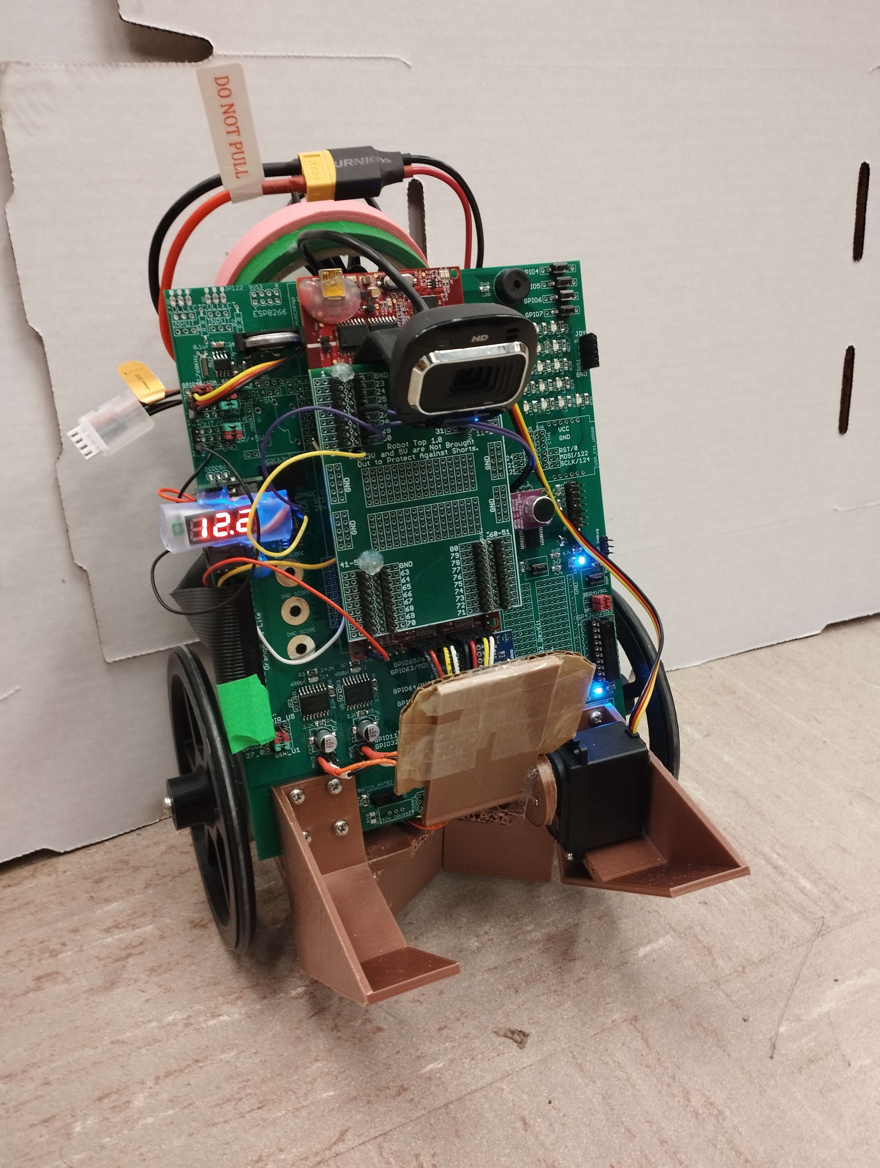
The project consists of a football (soccer) balancing robot or segbot used to score a golf ball into a goal. The project has two main systems, the segbot and the goal system.
The segbot system was programmed using a balancing control with a state space model of the robot, a turning control using a PID, and a speed control using a PD. Using these three controls the segbot was able to stand in its two wheels (balancing control) and advance in any directions (turning and speed control).
For the robot to hold the golf ball, a 3D model was designed using Fusion 360, Figure 1. The holding mechanism consist of a “V” shaped back structure to hold the ball centered, Figure 2, and a servomotor powered gate that closes the ball in between the mechanism, allowing the robot to transport the golf ball and shoot it when it has to.
The holding mechanism was mounted to the segbot as shown in Figure 3.
The sensor used to get the needed information from the environment was a Microsoft LifeCam HD-3000 controlled with a Raspberry PI 4. With that camara the segbot was able to detect the ball and its position, the marker on top of the goal and its position, and the walls of the field.
STATE MACHINE
The state machine implemented is shown in detail in Figure 4. It consists on the following procedures:
The robot is balancing waiting for the start command, G5-E5-C5 notes played in a row. Once the start command is given, the robot will start spinning around its edge looking for the ball.
If the robot does not see the ball after a full turn, it will do a search trajectory, consisting on going forward a certain distance and then turning again. The overall searching trajectory is a square, large enough to locate the ball at some point, considering the size of the field.
Once the ball is detected by the camera, the robot will go towards it centering the ball, so it is aligned to the holder mechanism. When the position of the ball is almost out of range of the camera (about 30cm away from the segbot), the robot will change to grab state in which it will advance about 30cm and then close the servo.
After this operation, the robot will go backwards to check if the grab was effectuated. If the robot detects the ball after going backwards it will repeat the grab, and if it does not see it, it will mean that the grab was successful.
After grabbing the ball, the segbot will then start looking for the marker situated on the goal. To do so it will use the same searching method as it used for the ball (360o turns and square search trajectory). Once it finds the marker, the vision system will estimate the distance to the marker. If the marker is too close to the robot, it will go backwards a certain distance to position to shoot. If it far enough it will wait for the shoot command.
The shoot command are another 3 notes (C5-E5-G5) played in sequence. Once the shoot command is given, the robot will accelerate until its distance to the goal is close enough to release the ball. Then, the servo will open and the segbot will stop immediately while the ball will roll towards the goal using the inertia moment applied by the robot.
Then the robot will wait in wait state for 10 seconds. If the ball misses the goal, nothing will happen in those 10 seconds, and the robot will start looking for the ball again to repeat the process. If the ball goes inside the ball, then the goal system will activate.
The goal system consists on another process driven by a F28379D Launchpad board. This system has two infrared sensos positioned at the sides of the goal that detect when the ball goes in. When it does, it sends via WiFi a command to a computer running a LabVIEW file. This file will play a song once the command is received. That way, once the robot scores, a song will start playing.
Using a beat detection function with the robot (similar to the sond detection for the start and shoot commands), it will start moving simulating a dance, celebrating that it scored.
There is a problem that needs to be taken into cosnideration during the process, that would be the robot collapsing into a wall. That is why there is a security measurement taken in case this happens. The cammera will be detecting how close to a wall the robot is by calculating what percentage of its vision field is colored like a wall. When the 67% of the vision field is a wall, that will make the robot go to the wall state.
In this state the robot will go backwards to get away from the wall and then it will do a 180o turn. If the robot was looking for the ball when it faced the wall, it will play a tone with its buzzer indicating that the ball needs to be relocated to a position where it can grab it. If the robot was looking for the goal, it will transition to the search goal state (as it will be holding the ball already). Lastly, if the robot was dancing, it will keep dancing when finished the 180o turn.
ALGORITHMS USED
One of the algorithms used to program our system was a state machine, using switch caseprogramming model. It consists of a mathematical model used to describe the behavior of a system. This type of algorithm allows the programmer to define a set of possible states for the system and specify the actions that should be taken when the system transitions from one state to another.
In our case, this algorithm was implemented to simplify and structure the functions of the system. That way we were able to program state by state without worrying of the impact in any other part of the code. To sum up, we first enter the desire case and program the function that the robot must accomplish. Once that task is done, a series of if statements are written, allowing the robot to change from the current state to the next one. We initialize the state variables in those ifstatements in case we want to enter the new state differently depending on the current state.
WEB EXPLAINING SWITCH – CASE ALGORYTHM
https://24ways.org/2018/state-machines-in-user-interfaces/
Another algorithm used will be working with sound. It will implement 3 FIR filters for shoot command for 3 different notes (C5 E5, G5). If first note is recognized it waits some time (3 sec) to get second note, then for third. The filters are sampled at 2kHz using EPWM3. Sample with 100 points was multiplied by fillter array and summed to obtain filtered output. last 10 points of data (10 summations) were used to find maximum value. If this maximum value is figher then some set floor value, the note ment to be detected. Another task is to make the segbot dance. Using FFT sampled at 10kHz and EPWM7, frequency with maximum amplitude can be recognized. The amplitudes of frequencies from 100Hz to 450Hz were summed. This boundaries were found to work best using spectrum analizer for differnt songs. By using audio with beat in defined region, the sum of low frequencies can be found and if the is larger then previous value by factor of 1.5 it was recognized as beat spike of the summation. The robot takes some action. To prevent detection false beats (people talking, noise) the lower limit for the beat was set.
The songs tested:
https://www.youtube.com/watch?v=fQ-Wfc70J9A
https://www.youtube.com/watch?v=-56Bzcj8ocY
For the goal system, it could be treated as a independent system. We use two IR sensors connect to the F29379D. Then the F29379D will send data to the LABVIEW on the computer via with WIFI module in ESP 8266.
For IR sensor, they are connecting to the ADC peripherals in F28379D chip. In this project, we select to use ADCD and its channels ADCND0,ADCIND1. The data received from these two channels are a number from 0 to 4096. It indicate the voltage of that pin. If some objects close to the IR sensor there will have a higher voltage of that pin. While the real range of the voltage is about 0-3V. So, we need to scale these number. (adcd0result/4096.0)*3.0 Then, either voltage results of these two sensors higher than 1.1 will make the variable called ‘goal’ change to 1. Here, we make a simple filter that making an average of 5 voltage reading to filter out the disturbs. The variable ‘goal’ is the data we want to send to the LABVIEW. After that, when ‘goal’ is equal to 1, a counter in CPU timer 2 (a interrupt function runs every 50ms) will start counting if it can be divided by 60 without remaining (which equal to 3 second) it will set the ‘goal’ back to 0
For ESP8266 we select GPIO 1 to communicate with F28379D chip. the WIFI module on ESP8266, we use TCP/IP AT command to communicate with UART. Under this project we only use ESP8266 to send data. But it can also receive the data (already included), the TCP/IP AT command include: AT+CWMODE、AT+CWJAP、AT+CIPSTA、AT+CIPMUX、AT+CIPSERVER、AT+CIPSEND. Here is the link with explanation for these command. In our code, we set the data send from the ESP 8266 start with '*a' to indicate the data follow is what we want the LABVIEW to recieve.
https://www.electronicshub.org/esp8266-at-commands/#TCPIP_AT_Commands
In LABVIEW VI, for TCP/IP communication start module, we set its IP address and port number same with those write in ESP8266 command. The LABVIEW will request the data every 1 second. While the data should start with ‘*a’ this is the mark that for the LABVIEW to know the data follow is that we want it to receive. In this project, once the data it receive is larger than 0.5. The LABVIEW will execute a sound file in WAV format. After finish the music, LABVIEW will repeat to request the data.


Comments