


Hardware components | ||||||
 |
| × | 1 | |||
 |
| × | 3 | |||
 |
| × | 2 | |||
 |
| × | 1 | |||
 |
| × | 1 | |||
 |
| × | 3 | |||
 |
| × | 2 | |||
This project was part of our practical work inside the Microprocessors class under the Electrical and Electronics Engineering degree at Universidade do Algarve.
We were introduced to Arduino philosophy based upon fisical computing and internet self-education, during class was introduced information about useful functions such as ISR (Interrupt Service Routines) through function attachInterrupt() as well as the utility of adopting FSM finite state machine (we already learned before) to the Arduino code on a way to reduce code and system resources, and keep the code much more simple to understand and use.
In a simple way a finite state machine (in Arduino) is a computer program that, at any moment, can be in one of a predetermined number of states.
The state is a specific action such for example “Wait for a certain button to be activated”, or “Moving the servo motor to 69°” . An Finite State Machine can replace in programming most of the While, For or similar structures.
ISRWith ISR (Interrupt Service Routines) we don't need code inside loop()
, turning the processor free to attend an interrupt quickly. The main limitation is the ATmega328 only attends one interruption at the same time, but on our case that's not a problem.
A real limitation for us is because millis()
doesn't work inside ISR due to the fact it uses interruptions to count - the only "clock" function that works during an interruption is delayMicroseconds()
but it is limited to about 16 miliseconds and in this case it is not enough. So we decided to call the functions of the FSM3 (state_2_next())
and FSM4 (state_2_out())
and digitalWrite (I)
inside loop()
.
In this problem, we intend to implement with the Arduino an FSM that commands an automatic gate, through two stimuli, a command and open&close micro-switch. The utilization of interrupts in this problem is with a objective the machine does not the resources consume.
The first step of our project was making the architecture design (attached) with the system inputs and outputs.
The second step was designing the state diagram (we used Moore diagram method) with the several states, inputs related to state transition and outputs linked to each state.
The third step was designing two flowcharts for each FSM, one for the next-state and another for the outputs.
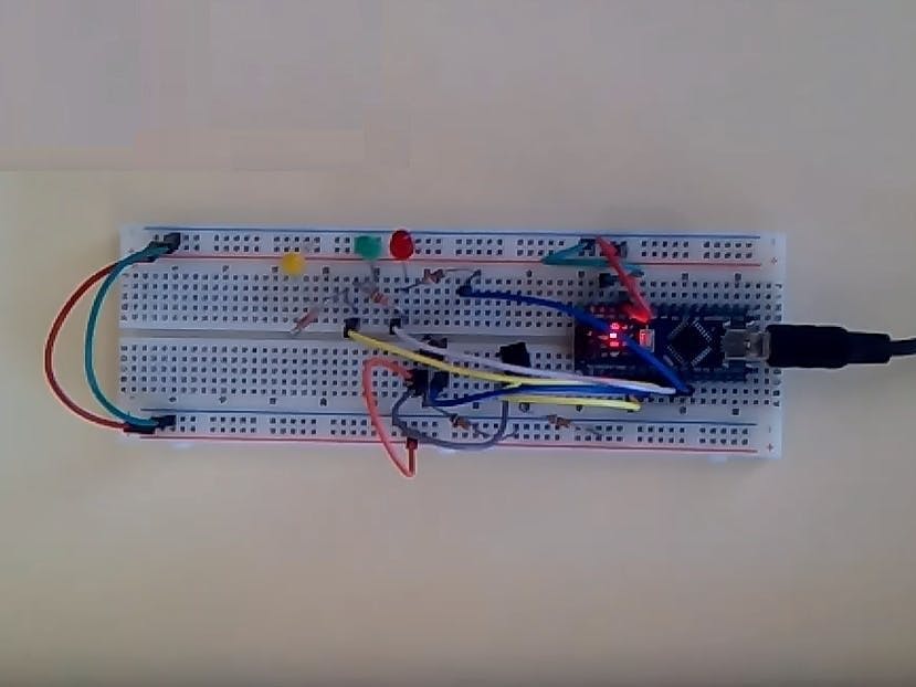
Finally, we have written the C code and have made the wiring diagram.


_3u05Tpwasz.png?auto=compress%2Cformat&w=40&h=40&fit=fillmax&bg=fff&dpr=2)
Comments