

Hardware components | ||||||
 |
| × | 1 | |||
| × | 1 | ||||
 |
| × | 1 | |||
 |
| × | 1 | |||
 |
| × | 1 | |||
| × | 1 | ||||
| × | 1 | ||||
 |
| × | 1 | |||
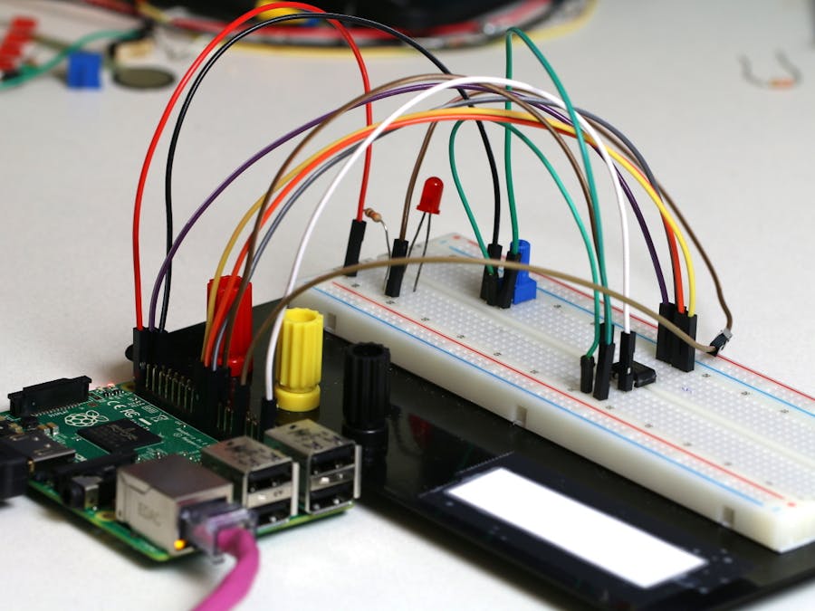
Potentiometer Sensor Sample
This sample shows how to connect a rotary potentiometer and LED to the Raspberry Pi 2. We use a SPI-based ADC (Analog to Digital Converter) to read values from the potentiometer and control an LED based on the knob position.
Parts needed
- 1 LED
- 1 330 Ω resistor
- 1 MCP3002 10-bit ADC or 1 MCP3208 12-bit ADC
- 1 10k Ω Trimmer Potentiometer
- Raspberry Pi2 board
- 1 breadboard and a couple of wires
- HDMI Monitor and HDMI cable
Parts Review
In this sample, you have the option of using either the MCP3002 or the MCP3208 ADC (Analog to Digital Converter). The main difference between these two is that the MCP3208 is a larger chip with more input channels and greater resolution. Both however will work fine for this sample.
Below are the pinouts of the MCP3002 and MCP3208 ADCs.
MCP3002 MCP3208
Raspberry Pi pinout
Wiring & Connections
MCP3002
If you chose to use the MCP3002, assemble the circuit as follows. Note that the wiper pin (the middle pin on the 10k potentiometer) should be connected to CH0 on MCP3002.
Detailed connection:
The MCP3002 should be connected as follows:
- MCP3002: VDD/VREF - 3.3V on Raspberry Pi 2
- MCP3002: CLK - “SPI0 SCLK” on Raspberry Pi 2
- MCP3002: Dout - “SPI0 MISO” on Raspberry Pi 2
- MCP3002: Din - “SPI0 MOSI” on Raspberry Pi 2
- MCP3002: CS/SHDN - “SPI0 CS0” on Raspberry Pi 2
- MCP3002: Vss - GND on Raspberry Pi 2
- MCP3002: CH0 - Potentiometer wiper pin
MCP3208
If you chose to use the MCP3208, assemble the circuit as follows. Note that the wiper pin (the middle pin on the 10k potentiometer) should be connected to CH0 on MCP3208.
Detailed connection:
The MCP3002 should be connected as follows:
- MCP3208: VDD - 3.3V on Raspberry Pi 2
- MCP3208: VREF - 3.3V on Raspberry Pi 2
- MCP3208: AGND - GND on Raspberry Pi 2
- MCP3208: CLK - “SPI0 SCLK” on Raspberry Pi 2
- MCP3208: Dout - “SPI0 MISO” on Raspberry Pi 2
- MCP3208: Din - “SPI0 MOSI” on Raspberry Pi 2
- MCP3208: CS/SHDN - “SPI0 CS0” on Raspberry Pi 2
- MCP3208: DGND - GND on Raspberry Pi 2
- MCP3002: CH0 - Potentiometer wiper pin
Building and running the sample
- Download the sample to your local machine
- Open
PotentiometerSensor\CS\PotentiometerSensorCS.csprojin Visual Studio - Find the
ADC_DEVICEvariable in MainPage.xaml.cs and change it to either AdcDevice.MCP3002 or AdcDevice.MCP3208 depending on the ADC you wired up above - Select
ARMfor the target architecture - Go to
Build -> Build Solution - Select
Remote Machinefrom the debug target - Hit F5 to deploy and debug. Enter the IP address of your device and select
Nonefor the authentication type
When you turn the potentiometer knob, you will see the number change on the screen indicating the potentiometer knob position. When the number is larger than half the ADC resolution (For MCP3002, this number is 512. For MCP3208, it’s 2048) the LED will turn ON. Otherwise, it turns OFF.
Let's look at the code
The code here performs two main tasks:
1. First the code initialize the SPI bus and LED GPIO Pin
2. Secondly, we read from the ADC at defined intervals and update the display
accordingly.
Let's start by digging into the initializations. The first thing we initialize is the GPIO LED in InitGPIO()
private void InitGpio(){ var gpio = GpioController.GetDefault(); /* Show an error if there is no GPIO controller */ if (gpio == null) { throw new Exception("There is no GPIO controller on this device"); } ledPin = gpio.OpenPin(LED_PIN); /* GPIO state is initially undefined, so we assign a default value before enabling as output */ ledPin.Write(GpioPinValue.High); ledPin.SetDriveMode(GpioPinDriveMode.Output); }
We start by retrieving the default GPIO controller on the device with the GpioController.GetDefault() function.
Since we connected the LED to GPIO 4, we open this pin on the GPIO controller.
Finally we write a default value to the pin before setting it as output.
Next, we initialize the SPI bus. This allows the RPi2 to communicate with the ADC to read in potentiometer positions.
private async Task InitSPI()
{
	try
	{
		var settings = new SpiConnectionSettings(SPI_CHIP_SELECT_LINE);
		settings.ClockFrequency = 500000;   /* 0.5MHz clock rate                                        */
		settings.Mode = SpiMode.Mode0;      /* The ADC expects idle-low clock polarity so we use Mode0  */

		string spiAqs = SpiDevice.GetDeviceSelector(SPI_CONTROLLER_NAME);
		var deviceInfo = await DeviceInformation.FindAllAsync(spiAqs);
		SpiADC = await SpiDevice.FromIdAsync(deviceInfo[0].Id, settings);
	}

	/* If initialization fails, display the exception and stop running */
	catch (Exception ex)
	{
		throw new Exception("SPI Initialization Failed", ex);
	}
}
- We start by specifying some configuration settings for our SPI bus:
- We specify which chip select line we want to use. We wired the ADC into chip select line 0, so that’s what we use here.
- The clock frequency is conservatively set to 0.5MHz, which is well within the ADC capabilities.
- settings.Mode is set to SpiMode.Mode0. This configures clock polarity and phase for the bus.
Next, we get the class selection string for our SPI controller. This controller controls the SPI lines on the exposed pin header. We then use the selection string to get the SPI bus controller matching our string name.
- Finally, we create a new SpiDevice with the settings and bus controller obtained previously.
After the initializations are complete, we create a periodic timer to read data every 100mS.
private async void InitAll()
{
	// ...

	/* Now that everything is initialized, create a timer so we read data every 500mS */
	periodicTimer = new Timer(this.Timer_Tick, null, 0, 100);

	StatusText.Text = "Status: Running";
}
This timer calls the Timer_Tick() function. Which starts by reading from the ADC:
public void ReadADC()
{
	byte[] readBuffer = new byte[3]; /* Buffer to hold read data*/
	byte[] writeBuffer = new byte[3] { 0x00, 0x00, 0x00 };

	/* Setup the appropriate ADC configuration byte */
	switch (ADC_DEVICE)
	{
		case AdcDevice.MCP3002:
			writeBuffer[0] = MCP3002_CONFIG;
			break;
		case AdcDevice.MCP3208:
			writeBuffer[0] = MCP3208_CONFIG;
			break;
	}

	SpiADC.TransferFullDuplex(writeBuffer, readBuffer); /* Read data from the ADC                           */
	adcValue = convertToInt(readBuffer);                /* Convert the returned bytes into an integer value */

	/* UI updates must be invoked on the UI thread */
	var task = this.Dispatcher.RunAsync(Windows.UI.Core.CoreDispatcherPriority.Normal, () =>
	{
		textPlaceHolder.Text = adcValue.ToString();         /* Display the value on screen                      */
	});
}
We first setup the writeBuffer with some configuration data to send to the ADC
Next we call SpiADC.TransferFullDuplex() to write the configuration data and read back the ADC results
Inside the convertToInt() function, we convert the returned byte array into a integer
Finally, we update the UI with the ADC result
Next, we control the LED based on the ADC result
/* Turn on/off the LED depending on the potentiometer position    */
private void LightLED()
{
	int adcResolution = 0;

	switch (ADC_DEVICE)
	{
		case AdcDevice.MCP3002:
			adcResolution = 1024;
			break;
		case AdcDevice.MCP3208:
			adcResolution = 4096;
			break;
	}

	/* Turn on LED if pot is rotated more halfway through its range */
	if (adcValue > adcResolution / 2)
	{
		ledPin.Write(GpioPinValue.Low);
	}
	/* Otherwise turn it off                                        */
	else
	{
		ledPin.Write(GpioPinValue.High);
	}
}- If the potentiometer is rotated more than halfway through its range, we turn on the LED. Otherwise it’s turned off.
That’s it! Now that you’ve learned how to use an ADC, you can hook up a variety of analog sensors to your Raspberry Pi 2.


Comments