


Hardware components | ||||||
 |
| × | 1 | |||
 |
| × | 1 | |||
 |
| × | 1 | |||
Software apps and online services | ||||||
 |
| |||||
 |
| |||||
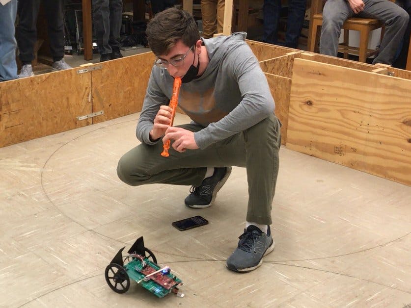
Shown below is an edited version of the team's in-class final presentation. It should demonstrate the function of the project clearly:
In addition, shown below here is a video explaining the integration of all the hardware and software that we used while creating our project:
Discussed here are a few paragraphs from each team member detailing their specific contributions to the project.
Michael: For our final project, Jonah and I programmed our robot to detect different musical notes from a recorder and move in certain ways based on those detected notes. We also used CPU2 on our red board to send those detected notes to LABVIEW and had LABVIEW display what notes were being detected. This second part of the project was the part that I worked on. The first thing that I worked on was getting the robot communicating with LABVIEW. This was done by using an ESP8266 chip soldered onto our green board.
Using code composer and LABVIEW, we initially programmed the chip to receive data sent from LABVIEW and send a string back to LABVIEW. We had to connect the chip to the same WIFI network as LABVIEW by inputting the same IP address and port for both the chip and LABVIEW to connect to. Then, using a similar VI to the one used in LABVIEW assignment 4, we sent a string of numbers out from LABVIEW to the ESP8266 chip and had the chip send a string, usually different letters, back to LABVIEW. We created an array that would be populated by characters that the ESP8266 chip would send to TeraTerm for things like the connection status, if the data was send or received correctly, and the string that was sent out by LABVIEW. Then, we scanned this array for the string that was sent out by LABVIEW and watched for it with watch expressions in code composer to make sure that the chip was correctly receiving data. Finally, the chip would then send out a string of characters back to LABVIEW and would be displayed on our VI. This was one of the more difficult tasks because sometimes the LABVIEW VI would timeout if the data wasn’t sent or sent incorrectly. It turned out that the VI needed a \r and a \n after our sent strings for it to receive and display properly in the VI, otherwise it would timeout. For an aesthetic look, I also created a musical scale that would display different notes that matched the string being sent.
The next thing I worked on was getting the red board’s CPU1 to communicate with CPU2. There was a lot of setup code involved for both CPUs, including CPU1 give CPU2 permission for controlling several GPIOs, several interrupts for CPU1 to send data over to CPU2, and having CPU2 wait for CPU1 to send over data. After adjusting our given CPU2 code to our needs, Jonah added his FFT and note recognition code into the CPU1 code and I added my sending to LABVIEW code into CPU2. At this point, we had some issues again with sending data to LABVIEW because the code was not correctly sending data to the chip to send to LABVIEW. We also had some issues with LABVIEW not connecting to the internet correctly, but we were able to get it all working in time before presenting it.
Jonah: For this final project, when we decided that the goal of the project was to create a robot that both responded to musical notes and displayed them on a screen via WiFi using a second CPU, we promptly split the project up into two parts. One part was to integrate the WiFi with CPU2 and communicate with LABView, and the other part was to use the main processor CPU1 to customize the performance of the robot. I undertook the latter of the two parts. Therefore, I was to write code for CPU1 which correctly heard musical notes, then took action based on those notes, all the while communicating these actions to CPU2 in order to eventually communicate with LABView.
Initially, I used TI's FFT (Fast Fourier Transform) library to switch back and forth between taking the FFT of two different 1024 data point arrays. While the FFT of the first array, called ping_array was being taken, 1024 data points of the microphone were being taken at a rate of 10kHz and being put into the other array: pong_array. Then, pong_array's FFT was taken while ping_array received new values. I struggled with getting the flow of this code to run correctly. However, eventually it was all integrated properly. At this point, by using watch expression in code composer I was able to fine tune the possible range of frequency indices that corresponded to all five tones I was working with. I also looked at the power of the signal produced by these tones and used a minimum power threshold to filter out insignificant noise. Once this was done, I successfully had the robot hearing musical notes and printing the correct note to the serial port.
I then had to add in the code we had used in a previous lab this semester that controlled the robot to move. Using PI control (proportional-integral control), these control laws used two controls, turn and v_ref, to control how the robot moves. By accounting for the error between the expected speed/turn values and the actual values computed using the encoder, simply adjusting v_ref for velocity and turn for rotation allows for complete control of the robot's motion. This was integrated into the code by initial the EPWM2 register as well as the EQEP peripheral on the launchpad to work with the motors and the encoder. Inside of one of the CPU timer's interrupt the control equations were run every 4 ms. Therefore, I simply added code that adjusted v_ref and turn accordingly based on each note, and the robot moved as I desired. The notes controlled the robot in this way:
C Note: Move forward. A Note: Move backward. F Note: Turn left. G Note: Turn right. Shrill note from mouth of recorder: Stop all motion.
At this point, the robot properly responded to the notes from the recorder, and all that was left for me to do was to integrate the communication with CPU2 into my code. This was tricky, but eventually it was done by populating an array called cpu1tocpu2 with values corresponding the index in the alphabet of each note. For example, if an A was played cpu1tocpu2[0] was set to 1.0, and if a G was played cpu1tocpu2[0] was set to 7.0. Arbitrarily the shrill note was set to 9.0. Then, if CPU2 received a 7.0 it knew to send the string 'G' to LABView. If it received 3.0, it would send 'C' and so on and so forth. This was the last modification I had to make, however some hiccups in WiFi communication forced me to slightly adjust some of the CPU2 code the day of our presentation as well. After this was done, we successfully controlled our robot with recorder notes and displayed them to the LABView screen using WiFi.
 //#############################################################################
// FILE:   labstarter_main.c
//
// TITLE:  Lab Starter
//#############################################################################

// Included Files
#include <stdio.h>
#include <stdlib.h>
#include <stdarg.h>
#include <string.h>
#include <math.h>
#include <limits.h>
#include "F28x_Project.h"
#include "driverlib.h"
#include "device.h"
#include "f28379dSerial.h"
#include "dsp.h"
#include "fpu32/fpu_rfft.h"
// For IPC
#include "F2837xD_Ipc_drivers.h"

#define PI          3.1415926535897932384626433832795
#define TWOPI       6.283185307179586476925286766559
#define HALFPI      1.5707963267948966192313216916398
#define FEETINONEMETER 3.28083989501312
#define MIN(A,B)        (((A) < (B)) ? (A) : (B));

//*****************************************************************************
// the defines for FFT
//*****************************************************************************
#define RFFT_STAGES     10
#define RFFT_SIZE       (1 << RFFT_STAGES)

//*****************************************************************************
// the globals
//*****************************************************************************
#ifdef __cplusplus
#pragma DATA_SECTION("FFT_buffer_2")
#else
#pragma DATA_SECTION(pwrSpec, "FFT_buffer_2")
#endif
float pwrSpec[(RFFT_SIZE/2)+1];
float maxpwr = 0;
int16_t maxpwrindex = 0;

#ifdef __cplusplus
#pragma DATA_SECTION("FFT_buffer_2")
#else
#pragma DATA_SECTION(test_output, "FFT_buffer_2")
#endif
float test_output[RFFT_SIZE];


#ifdef __cplusplus
#pragma DATA_SECTION("FFT_buffer_1")
#else
#pragma DATA_SECTION(ping_input, "FFT_buffer_1")
#endif
float ping_input[RFFT_SIZE];

#ifdef __cplusplus
#pragma DATA_SECTION("FFT_buffer_1")
#else
#pragma DATA_SECTION(pong_input, "FFT_buffer_1")
#endif
float pong_input[RFFT_SIZE];

#ifdef __cplusplus
#pragma DATA_SECTION("FFT_buffer_2")
#else
#pragma DATA_SECTION(RFFTF32Coef,"FFT_buffer_2")
#endif //__cplusplus
//! \brief Twiddle Factors
//!
float RFFTF32Coef[RFFT_SIZE];


//! \brief Object of the structure RFFT_F32_STRUCT
//!
RFFT_F32_STRUCT rfft;

//! \brief Handle to the RFFT_F32_STRUCT object
//!
RFFT_F32_STRUCT_Handle hnd_rfft = &rfft;


// Interrupt Service Routines predefinition
__interrupt void cpu_timer0_isr(void);
__interrupt void cpu_timer1_isr(void);
__interrupt void cpu_timer2_isr(void);
__interrupt void SWI_isr(void);
__interrupt void ADCB_isr(void); //Define interrupt for ADCB
__interrupt void SPIB_isr(void); //Predefines the SPI interrupt
__interrupt void CPU2toCPU1IPC0(void);


float *cpu2tocpu1; //float pointer for the location CPU2 will give data to CPU1
float *cpu1tocpu2; //float pointer for the location CPU1 will give data to CPU2
char *commandtoCPU2;


void serialRXA(serial_t *s, char data);
void setEPWM2A(float controleffort); //Function definition to pass values EPWM2A (right motor)
void setEPWM2B(float controleffort); //Function definition to pass values EPWM2B (left motor)
float saturate(float input, float saturation_limit); //Function definition for saturate function
void init_eQEPs(void); //Function definition to initialize  eQEP
float readEncLeft(void); //Function definition to read left encoder
float readEncRight(void); //Function definition to read right encoder
void setupSpib(void); //Predefines the SPI setup function

// Count variables
uint32_t numTimer0calls = 0;
uint32_t numSWIcalls = 0;
uint32_t numRXA = 0;
uint16_t UARTPrint = 0;

uint32_t numCPU2COMs = 0;
float receivefloats[4] = {0,0,0,0};
float sendfloats[4] = {0,0,0,0};
uint32_t timecounter = 0;

uint32_t ADCB_ISR_calls = 0; //Counts number of times ADCB interrupt was called
int16_t pingPong = 1;
int16_t runPong = 0;
int16_t runPing = 0;
int16_t ping_index = 0;
int16_t pong_index = 0;
int16_t powerThreshold = 100;
int16_t G_Low_Threshold = 75;
int16_t G_High_Threshold = 83;
int16_t A_Low_Threshold = 86;
int16_t A_High_Threshold = 95;
int16_t F_Low_Threshold = 69;
int16_t F_High_Threshold = 77;
int16_t C_Low_Threshold = 103;
int16_t C_High_Threshold = 113;
int16_t Stop_Low_Threshold = 118;
int16_t Stop_High_Threshold = 126;


int16_t spivalue1 = 0;
int16_t spivalue2 = 0;
float theta_l = 0; //Stores left encoder value
float theta_r = 0; //Stores right encoder value
float rad_to_feet = 0.19916351; //=1/5.021 is our conversion factor determined for radians to feet based on wheel geometry
float right_dist = 0; //Used to store the distance traveled by the right wheel
float left_dist = 0; //Used to store the distance traveled by the left wheel
float uLeft = 5; //Passed to left motor speed
float uRight = 5; //Passed to right motor speed
float PosLeft_K = 0; //Stores current left position
float PosLeft_K_1 = 0; //Stores past left position
float PosRight_K = 0; //Store current right position
float PosRight_K_1 = 0; //Stores past right position
float vel_right = 0; //Stores right wheel linear velocity
float vel_left = 0; //Stores left wheel linear velocity
float v_ref = 0; //Stores velocity to be passed to robot
float ki = 25; //Integral control constant
float kp = 3; //Proportional control constant
float ek_r = 0; //Right wheel control error
float ek_1_r = 0; //Previous right wheel control error
float ik_r = 0; //Right signal passed through integral
float ik_1_r = 0; //Previous right signal passed through integral
float ek_l = 0;  //Left wheel control error
float ek_1_l = 0; //Previous left wheel control error
float ik_l = 0; //Left signal passed through integral
float ik_1_l = 0; //Previous left signal passed through integral
float theta_l_1 = 0; //Previous left angular position
float theta_r_1 = 0; //Previous right angular position
float x_r_1 = 0; //Previous robot x position
float y_r_1 = 0; //Previous robot y position
float KP_turn = 3; //Proportional turn constant
float e_turn = 0; //Turn error
float turn = 0; //Turn setpoint
float W_r = 0.57743; //Robot width
float R_wh = 0.19583; //Wheel radius
float phi_r = 0; //Robot pose angle
float x_r = 0; //Robot Pose X Coordinate
float y_r = 0; //Robot Pose Y Coordinate
float theta_avg = 0; //Average angular position
float theta_dot_avg = 0; //Average angular velocity
float theta_dot_l = 0; //Left angular velocity
float theta_dot_r = 0; //Right angular velocity
float y_dot_r = 0; //Y linear velocity
float x_dot_r = 0; //X linear velocity
int16_t updown = 1; //Used to decrease/increase PWM signal
int16_t PWM1 = 0; //Used to send values to PWM1 on DAN28027 chip
int16_t PWM2 = 0; //Used to send values to PWM2 on DAN28027 chip
int16_t SPIB_isr_calls = 0; //Counts number of times SPIB isr function is called
int16_t garbage = 0; //Used for useless SPI outputs
int16_t ADC1 = 0; //ADC1 SPI Output
int16_t ADC2 = 0; //ADC2 SPI Output
float ADC1_v = 0; //ADC1 SPI Output in volts
float ADC2_v = 0; //ADC2 SPI Output in volts
int16_t ACCEL_XOUT_RAW = 0; //Used to read the raw X acceleration from the SPI
int16_t ACCEL_YOUT_RAW = 0; //Used to read the raw Y acceleration from the SPI
int16_t ACCEL_ZOUT_RAW = 0; //Used to read the raw Z acceleration from the SPI
int16_t TEMP_OUT_RAW = 0; //Used to read the temperature from the SPI
int16_t GYRO_XOUT_RAW = 0; //Used to read the raw X gyro data from the SPI
int16_t GYRO_YOUT_RAW = 0; //Used to read the raw Y gyro data from the SPI
int16_t GYRO_ZOUT_RAW = 0; //Used to read the raw Z gyro data from the SPI

float ACCEL_XOUT = 0; //Used to store the converted X acceleration data in the range (-4,4) with units of g
float ACCEL_YOUT = 0; //Used to store the converted Y acceleration data in the range (-4,4) with units of g=(-4g,4g)
float ACCEL_ZOUT = 0; //Used to store the converted Z acceleration data in the range (-4,4) with units of g
float GYRO_XOUT = 0; //Used to store the converted X gyro data in the range (-250,250) with units of deg/sec
float GYRO_YOUT = 0; //Used to store the converted Y gyro data in the range  (-250,250) with units of deg/sec
float GYRO_ZOUT = 0; //Used to store the converted Z gyro data in the range  (-250,250) with units of deg/sec


void main(void)
{
    // PLL, WatchDog, enable Peripheral Clocks
    // This example function is found in the F2837xD_SysCtrl.c file.
    InitSysCtrl();

    InitIpc();

    commandtoCPU2 = (char*) 0x3FFFC;  // in RAM that CPU1 can R/W but CPU2 can only read.
    //location of cpu2tocpu1 ram
    cpu2tocpu1 = (float*) 0x3F800;
    cpu1tocpu2 = (float*) 0x3FC00;

    commandtoCPU2[0] = 'W';  // W for CPU2 wait

    //     Comment this when use CCS for debugging
//            #ifdef _FLASH
//                // Send boot command to allow the CPU2 application to begin execution


        //         IPCBootCPU2(C1C2_BROM_BOOTMODE_BOOT_FROM_FLASH);


//            #else
//                // Send boot command to allow the CPU2 application to begin execution
//                IPCBootCPU2(C1C2_BROM_BOOTMODE_BOOT_FROM_RAM);
//            #endif
//  Or when you want to run CPU2 from its flash you free run CPU2 and just run IPCBootCPU2 from Flash command.  Actually I do not know when you need boot from RAM ???


    InitGpio();

    // Blue LED on LaunchPad
    GPIO_SetupPinMux(31, GPIO_MUX_CPU1, 0);
    GPIO_SetupPinOptions(31, GPIO_OUTPUT, GPIO_PUSHPULL);
    GpioDataRegs.GPASET.bit.GPIO31 = 1;

    // Red LED on LaunchPad
    GPIO_SetupPinMux(34, GPIO_MUX_CPU2, 0);
    GPIO_SetupPinOptions(34, GPIO_OUTPUT, GPIO_PUSHPULL);
    //GpioDataRegs.GPBSET.bit.GPIO34 = 1;

    // LED1 and PWM Pin
    GPIO_SetupPinMux(22, GPIO_MUX_CPU1, 0);
    GPIO_SetupPinOptions(22, GPIO_OUTPUT, GPIO_PUSHPULL);
    GpioDataRegs.GPACLEAR.bit.GPIO22 = 1;

    // LED2
    GPIO_SetupPinMux(94, GPIO_MUX_CPU1, 0);
    GPIO_SetupPinOptions(94, GPIO_OUTPUT, GPIO_PUSHPULL);
    GpioDataRegs.GPCCLEAR.bit.GPIO94 = 1;

    // LED3
    GPIO_SetupPinMux(95, GPIO_MUX_CPU1, 0);
    GPIO_SetupPinOptions(95, GPIO_OUTPUT, GPIO_PUSHPULL);
    GpioDataRegs.GPCCLEAR.bit.GPIO95 = 1;

    // LED4
    GPIO_SetupPinMux(97, GPIO_MUX_CPU1, 0);
    GPIO_SetupPinOptions(97, GPIO_OUTPUT, GPIO_PUSHPULL);
    GpioDataRegs.GPDCLEAR.bit.GPIO97 = 1;

    // LED5
    GPIO_SetupPinMux(111, GPIO_MUX_CPU1, 0);
    GPIO_SetupPinOptions(111, GPIO_OUTPUT, GPIO_PUSHPULL);
    GpioDataRegs.GPDCLEAR.bit.GPIO111 = 1;

    // LED6
    GPIO_SetupPinMux(130, GPIO_MUX_CPU1, 0);
    GPIO_SetupPinOptions(130, GPIO_OUTPUT, GPIO_PUSHPULL);
    GpioDataRegs.GPECLEAR.bit.GPIO130 = 1;

    // LED7
    GPIO_SetupPinMux(131, GPIO_MUX_CPU1, 0);
    GPIO_SetupPinOptions(131, GPIO_OUTPUT, GPIO_PUSHPULL);
    GpioDataRegs.GPECLEAR.bit.GPIO131 = 1;

    // LED8
    GPIO_SetupPinMux(25, GPIO_MUX_CPU1, 0);
    GPIO_SetupPinOptions(25, GPIO_OUTPUT, GPIO_PUSHPULL);
    GpioDataRegs.GPACLEAR.bit.GPIO25 = 1;

    // LED9
    GPIO_SetupPinMux(26, GPIO_MUX_CPU1, 0);
    GPIO_SetupPinOptions(26, GPIO_OUTPUT, GPIO_PUSHPULL);
    GpioDataRegs.GPACLEAR.bit.GPIO26 = 1;

    // LED10
    GPIO_SetupPinMux(27, GPIO_MUX_CPU1, 0);
    GPIO_SetupPinOptions(27, GPIO_OUTPUT, GPIO_PUSHPULL);
    GpioDataRegs.GPACLEAR.bit.GPIO27 = 1;

    // LED11
    GPIO_SetupPinMux(60, GPIO_MUX_CPU1, 0);
    GPIO_SetupPinOptions(60, GPIO_OUTPUT, GPIO_PUSHPULL);
    GpioDataRegs.GPBCLEAR.bit.GPIO60 = 1;

    // LED12
    GPIO_SetupPinMux(61, GPIO_MUX_CPU1, 0);
    GPIO_SetupPinOptions(61, GPIO_OUTPUT, GPIO_PUSHPULL);
    GpioDataRegs.GPBCLEAR.bit.GPIO61 = 1;

    // LED13
    GPIO_SetupPinMux(157, GPIO_MUX_CPU1, 0);
    GPIO_SetupPinOptions(157, GPIO_OUTPUT, GPIO_PUSHPULL);
    GpioDataRegs.GPECLEAR.bit.GPIO157 = 1;

    // LED14
    GPIO_SetupPinMux(158, GPIO_MUX_CPU1, 0);
    GPIO_SetupPinOptions(158, GPIO_OUTPUT, GPIO_PUSHPULL);
    GpioDataRegs.GPECLEAR.bit.GPIO158 = 1;

    // LED15
    GPIO_SetupPinMux(159, GPIO_MUX_CPU1, 0);
    GPIO_SetupPinOptions(159, GPIO_OUTPUT, GPIO_PUSHPULL);
    GpioDataRegs.GPECLEAR.bit.GPIO159 = 1;

    // LED16
    GPIO_SetupPinMux(160, GPIO_MUX_CPU1, 0);
    GPIO_SetupPinOptions(160, GPIO_OUTPUT, GPIO_PUSHPULL);
    GpioDataRegs.GPFCLEAR.bit.GPIO160 = 1;

    //DRV8874 #1 DIR  Direction
    GPIO_SetupPinMux(29, GPIO_MUX_CPU1, 0);
    GPIO_SetupPinOptions(29, GPIO_OUTPUT, GPIO_PUSHPULL);
    GpioDataRegs.GPASET.bit.GPIO29 = 1;

    //DRV8874 #2 DIR  Direction
    GPIO_SetupPinMux(32, GPIO_MUX_CPU1, 0);
    GPIO_SetupPinOptions(32, GPIO_OUTPUT, GPIO_PUSHPULL);
    GpioDataRegs.GPBSET.bit.GPIO32 = 1;

    //MPU9250  CS  Chip Select
    GPIO_SetupPinMux(66, GPIO_MUX_CPU1, 0);
    GPIO_SetupPinOptions(66, GPIO_OUTPUT, GPIO_PUSHPULL);
    GpioDataRegs.GPCSET.bit.GPIO66 = 1;

    //WIZNET  CS  Chip Select
    GPIO_SetupPinMux(125, GPIO_MUX_CPU1, 0);
    GPIO_SetupPinOptions(125, GPIO_OUTPUT, GPIO_PUSHPULL);
    GpioDataRegs.GPDSET.bit.GPIO125 = 1;

    //SPIRAM  CS  Chip Select
    GPIO_SetupPinMux(19, GPIO_MUX_CPU1, 0);
    GPIO_SetupPinOptions(19, GPIO_OUTPUT, GPIO_PUSHPULL);
    GpioDataRegs.GPASET.bit.GPIO19 = 1;

    //PushButton 1
    GPIO_SetupPinMux(4, GPIO_MUX_CPU1, 0);
    GPIO_SetupPinOptions(4, GPIO_INPUT, GPIO_PULLUP);

    //PushButton 2
    GPIO_SetupPinMux(5, GPIO_MUX_CPU1, 0);
    GPIO_SetupPinOptions(5, GPIO_INPUT, GPIO_PULLUP);

    //PushButton 3
    GPIO_SetupPinMux(6, GPIO_MUX_CPU1, 0);
    GPIO_SetupPinOptions(6, GPIO_INPUT, GPIO_PULLUP);

    //PushButton 4
    GPIO_SetupPinMux(7, GPIO_MUX_CPU1, 0);
    GPIO_SetupPinOptions(7, GPIO_INPUT, GPIO_PULLUP);

    //Joy Stick Pushbutton
    GPIO_SetupPinMux(8, GPIO_MUX_CPU1, 0);
    GPIO_SetupPinOptions(8, GPIO_INPUT, GPIO_PULLUP);

    EALLOW;
    GpioCtrlRegs.GPDPUD.bit.GPIO122 = 0; // Enable Pull-ups on SPI PINs Recommended by TI for SPI Pins
    GpioCtrlRegs.GPDPUD.bit.GPIO123 = 0;
    GpioCtrlRegs.GPDPUD.bit.GPIO124 = 0;
    GpioCtrlRegs.GPDQSEL2.bit.GPIO122 = 3; // Set prequalifier for SPI PINS
    GpioCtrlRegs.GPDQSEL2.bit.GPIO123 = 3; // The prequalifier eliminates short noise spikes
    GpioCtrlRegs.GPDQSEL2.bit.GPIO124 = 3; // by making sure the serial pin stays low for 3 clock periods.
    EDIS;

    // Clear all interrupts and initialize PIE vector table:
    // Disable CPU interrupts
    DINT;

    // Initialize the PIE control registers to their default state.
    // The default state is all PIE interrupts disabled and flags
    // are cleared.
    // This function is found in the F2837xD_PieCtrl.c file.
    InitPieCtrl();

    // Disable CPU interrupts and clear all CPU interrupt flags:
    IER = 0x0000;
    IFR = 0x0000;

    // Initialize the PIE vector table with pointers to the shell Interrupt
    // Service Routines (ISR).
    // This will populate the entire table, even if the interrupt
    // is not used in this example.  This is useful for debug purposes.
    // The shell ISR routines are found in F2837xD_DefaultIsr.c.
    // This function is found in F2837xD_PieVect.c.
    InitPieVectTable();

    // Interrupts that are used in this example are re-mapped to
    // ISR functions found within this project
    EALLOW;  // This is needed to write to EALLOW protected registers
    PieVectTable.TIMER0_INT = &cpu_timer0_isr;
    PieVectTable.TIMER1_INT = &cpu_timer1_isr;
    PieVectTable.TIMER2_INT = &cpu_timer2_isr;
    PieVectTable.SCIA_RX_INT = &RXAINT_recv_ready;
    //PieVectTable.SCIC_RX_INT = &RXCINT_recv_ready;
    PieVectTable.SCID_RX_INT = &RXDINT_recv_ready;
    PieVectTable.SCIA_TX_INT = &TXAINT_data_sent;
    //PieVectTable.SCIC_TX_INT = &TXCINT_data_sent;
    PieVectTable.SCID_TX_INT = &TXDINT_data_sent;
    PieVectTable.IPC0_INT = &CPU2toCPU1IPC0;
    PieVectTable.ADCB1_INT = &ADCB_isr; //Enables ADCB interrupt for when it is needed

    PieVectTable.EMIF_ERROR_INT = &SWI_isr;
    EDIS;    // This is needed to disable write to EALLOW protected registers


    // Initialize the CpuTimers Device Peripheral. This function can be
    // found in F2837xD_CpuTimers.c
    InitCpuTimers();

    // Configure CPU-Timer 0, 1, and 2 to interrupt every second:
    // 200MHz CPU Freq, 1 second Period (in uSeconds)
    ConfigCpuTimer(&CpuTimer0, 200, 4000);
    ConfigCpuTimer(&CpuTimer1, 200, 40000);
    ConfigCpuTimer(&CpuTimer2, 200, 222000);

    // Enable CpuTimer Interrupt bit TIE
    CpuTimer0Regs.TCR.all = 0x4000;
    CpuTimer1Regs.TCR.all = 0x4000;
    CpuTimer2Regs.TCR.all = 0x4000;

    init_serial(&SerialA,115200,serialRXA);
    init_eQEPs(); //Initialize the eQEP
    setupSpib(); //Setup the SPI

    EALLOW;
    //EPWM 2 Initializations used to pass PWM values to motors
    EPwm2Regs.TBCTL.bit.FREE_SOFT = 3;
    EPwm2Regs.TBCTL.bit.CLKDIV = 0;
    EPwm2Regs.TBCTL.bit.CTRMODE = 0;
    EPwm2Regs.TBCTL.bit.PHSEN = 0;
    EPwm2Regs.TBCTR = 0;
    EPwm2Regs.TBPRD = 2500; //50 MHz/20KHz=2500 50 MHz is frequency of clock source being counted, 20 KHz is desired
    EPwm2Regs.CMPA.bit.CMPA = 0; //Start duty cycle at 0
    EPwm2Regs.AQCTLA.bit.CAU = 1;
    EPwm2Regs.AQCTLA.bit.ZRO = 2;
    EPwm2Regs.TBPHS.bit.TBPHS = 0;
    EPwm2Regs.CMPB.bit.CMPB = 0; //The following three bits are defined again for EPWM2B
    EPwm2Regs.AQCTLB.bit.CBU = 1;
    EPwm2Regs.AQCTLB.bit.ZRO = 2;
    GPIO_SetupPinMux(2, GPIO_MUX_CPU1, 1); //GPIO PinName, CPU, Mux Index
    GPIO_SetupPinMux(3, GPIO_MUX_CPU1, 1); //GPIO PinName, CPU, Mux Index


    EPwm5Regs.ETSEL.bit.SOCAEN = 0; // Disable SOC on A group
    EPwm5Regs.TBCTL.bit.CTRMODE = 3; // freeze counter
    EPwm5Regs.ETSEL.bit.SOCASEL = 2; // Select Event when counter equal to PRD
    EPwm5Regs.ETPS.bit.SOCAPRD = 1; // Generate pulse on 1st event (“pulse” is the same as “trigger”)
    EPwm5Regs.TBCTR = 0x0; // Clear counter
    EPwm5Regs.TBPHS.bit.TBPHS = 0x0000; // Phase is 0
    EPwm5Regs.TBCTL.bit.PHSEN = 0; // Disable phase loading
    EPwm5Regs.TBCTL.bit.CLKDIV = 0; //Divide by zero for exercises 1-3 and end of exercise 4
    //EPwm5Regs.TBCTL.bit.CLKDIV = 2; //Divide by 4 to sample at 4 kHz for start of exercise 4
    //EPwm5Regs.TBPRD = 50000;  // Use for all except end of exercise 4. Set Period to 1ms sample (or.25 ms for start of exercise 4.)  Input clock is 50MHz.
    EPwm5Regs.TBPRD = 5000; //Use for end of exercise 4. 5000 instead of 50000 results in 10 KHz frequency of sampling.
    // Notice here that we are not setting CMPA or CMPB because we are not using the PWM signal
    EPwm5Regs.ETSEL.bit.SOCAEN = 1; //enable SOCA
    EPwm5Regs.TBCTL.bit.CTRMODE = 0; //unfreeze, and enter up count mode
    EDIS;

    EALLOW;
    //write configurations for all ADCs  ADCA, ADCB, ADCC, ADCD
    AdcbRegs.ADCCTL2.bit.PRESCALE = 6; //set ADCCLK divider to /4
    AdcaRegs.ADCCTL2.bit.PRESCALE = 6; //set ADCCLK divider to /4
    AdcSetMode(ADC_ADCB, ADC_RESOLUTION_12BIT, ADC_SIGNALMODE_SINGLE);  //read calibration settings
    AdcSetMode(ADC_ADCA, ADC_RESOLUTION_12BIT, ADC_SIGNALMODE_SINGLE);  //read calibration settings
    //Set pulse positions to late
    AdcaRegs.ADCCTL1.bit.INTPULSEPOS = 1;
    AdcbRegs.ADCCTL1.bit.INTPULSEPOS = 1;
    //power up the ADCs
    AdcaRegs.ADCCTL1.bit.ADCPWDNZ = 1;
    AdcbRegs.ADCCTL1.bit.ADCPWDNZ = 1;
    //delay for 1ms to allow ADC time to power up
    DELAY_US(1000);

    //ADCA
    AdcaRegs.ADCSOC0CTL.bit.CHSEL = 2;  //SOC0 will convert Channel you choose Does not have to be A0
                                            //For us we had ADCA SOC0 convert channel 2
    AdcaRegs.ADCSOC0CTL.bit.ACQPS = 99; //sample window is acqps + 1 SYSCLK cycles = 500ns
    AdcaRegs.ADCSOC0CTL.bit.TRIGSEL = 13;// EPWM5 ADCSOCA or another trigger you choose will trigger SOC0
    AdcaRegs.ADCSOC1CTL.bit.CHSEL = 3;  //SOC1 will convert Channel you choose Does not have to be A1
                                            //Similarly SOC1 converted channel 3
    AdcaRegs.ADCSOC1CTL.bit.ACQPS = 99; //sample window is acqps + 1 SYSCLK cycles = 500ns
    AdcaRegs.ADCSOC1CTL.bit.TRIGSEL = 13;// EPWM5 ADCSOCA or another trigger you choose will trigger SOC1
    AdcaRegs.ADCINTSEL1N2.bit.INT1SEL = 1; //set to last SOC that is converted and it will set INT1 flag ADCA1
                                               //Last SOC was SOC1
    AdcaRegs.ADCINTSEL1N2.bit.INT1E = 1;   //enable INT1 flag
    AdcaRegs.ADCINTFLGCLR.bit.ADCINT1 = 1; //make sure INT1 flag is cleared


    //ADCB
    AdcbRegs.ADCSOC0CTL.bit.CHSEL = 4;  //SOC0 will convert Channel you choose Does not have to be B0
                                            //Only SOC0 is used, and it will convert channel 4
    AdcbRegs.ADCSOC0CTL.bit.ACQPS = 99; //sample window is acqps + 1 SYSCLK cycles = 500ns
    AdcbRegs.ADCSOC0CTL.bit.TRIGSEL = 13; // EPWM5 ADCSOCA or another trigger you choose will trigger SOC0
    //AdcbRegs.ADCSOC1CTL.bit.CHSEL = 1;  //SOC1 will convert Channel you choose Does not have to be B1
    //AdcbRegs.ADCSOC1CTL.bit.ACQPS = 99; //sample window is acqps + 1 SYSCLK cycles = 500ns
    //AdcbRegs.ADCSOC1CTL.bit.TRIGSEL = 13; // EPWM5 ADCSOCA or another trigger you choose will trigger SOC1
    //AdcbRegs.ADCSOC2CTL.bit.CHSEL = 2;  //SOC2 will convert Channel you choose Does not have to be B2
    //AdcbRegs.ADCSOC2CTL.bit.ACQPS = 99; //sample window is acqps + 1 SYSCLK cycles = 500ns
    //AdcbRegs.ADCSOC2CTL.bit.TRIGSEL = 13; // EPWM5 ADCSOCA or another trigger you choose will trigger SOC2
    //AdcbRegs.ADCSOC3CTL.bit.CHSEL = 3;  //SOC3 will convert Channel you choose Does not have to be B3
    //AdcbRegs.ADCSOC3CTL.bit.ACQPS = 99; //sample window is acqps + 1 SYSCLK cycles = 500ns
    //AdcbRegs.ADCSOC3CTL.bit.TRIGSEL = 13; // EPWM5 ADCSOCA or another trigger you choose will trigger SOC3
    AdcbRegs.ADCINTSEL1N2.bit.INT1SEL = 0; //set to last SOC that is converted and it will set INT1 flag ADCB1
                                               //SOC0 was last SOC
    AdcbRegs.ADCINTSEL1N2.bit.INT1E = 1;   //enable INT1 flag
    AdcbRegs.ADCINTFLGCLR.bit.ADCINT1 = 1; //make sure INT1 flag is cleared
    EDIS;

    GPIO_SetupPinMux(9, GPIO_MUX_CPU1, 0);  // Set as GPIO9 and used as DAN28027 SS
    GPIO_SetupPinOptions(9, GPIO_OUTPUT, GPIO_PUSHPULL);  // Make GPIO9 an Output Pin
    GpioDataRegs.GPASET.bit.GPIO9 = 1;  //Initially Set GPIO9/SS High so DAN28027 is not selected

    GPIO_SetupPinMux(66, GPIO_MUX_CPU1, 0);  // Set as GPIO66 and used as MPU-9250 SS
    GPIO_SetupPinOptions(66, GPIO_OUTPUT, GPIO_PUSHPULL);  // Make GPIO66 an Output Pin
    GpioDataRegs.GPCSET.bit.GPIO66 = 1;  //Initially Set GPIO66/SS High so MPU-9250 is not selected

    GPIO_SetupPinMux(63, GPIO_MUX_CPU1, 15);  //Set GPIO63 pin to SPISIMOB
    GPIO_SetupPinMux(64, GPIO_MUX_CPU1, 15);  //Set GPIO64 pin to SPISOMIB
    GPIO_SetupPinMux(65, GPIO_MUX_CPU1, 15);  //Set GPIO65 pin to SPICLKB

    EALLOW;
    GpioCtrlRegs.GPBPUD.bit.GPIO63   = 0;  // Enable Pull-ups on SPI PINs Recommended by TI for SPI Pins
    GpioCtrlRegs.GPCPUD.bit.GPIO64   = 0;
    GpioCtrlRegs.GPCPUD.bit.GPIO65   = 0;
    GpioCtrlRegs.GPBQSEL2.bit.GPIO63 = 3;  // Set I/O pin to asynchronous mode recommended for SPI
    GpioCtrlRegs.GPCQSEL1.bit.GPIO64 = 3;  // Set I/O pin to asynchronous mode recommended for SPI
    GpioCtrlRegs.GPCQSEL1.bit.GPIO65 = 3;  // Set I/O pin to asynchronous mode recommended for SPI
    EDIS;


    SpibRegs.SPICCR.bit.SPISWRESET = 0;  // Put SPI in Reset

    SpibRegs.SPICTL.bit.CLK_PHASE = 1;  //This happens to be the mode for both the DAN28027 and
    SpibRegs.SPICCR.bit.CLKPOLARITY = 0;  //The MPU-9250,  Mode 01.
    SpibRegs.SPICTL.bit.MASTER_SLAVE = 1;  // Set to SPI Master
    SpibRegs.SPICCR.bit.SPICHAR = 15;  // Set to transmit and receive 16 bits each write to SPITXBUF (f in hex)
    SpibRegs.SPICTL.bit.TALK = 1;  // Enable transmission
    SpibRegs.SPIPRI.bit.FREE = 1;  // Free run, continue SPI operation
    SpibRegs.SPICTL.bit.SPIINTENA = 0;  // Disables the SPI interrupt

    SpibRegs.SPIBRR.bit.SPI_BIT_RATE = 50; // Set SCLK bit rate to 1 MHz so 1us period.  SPI base clock is
    // 50MHZ.  And this setting divides that base clock to create SCLK’s period
    SpibRegs.SPISTS.all = 0x0000;  // Clear status flags just in case they are set for some reason

    SpibRegs.SPIFFTX.bit.SPIRST = 1;// Pull SPI FIFO out of reset, SPI FIFO can resume transmit or receive.
    SpibRegs.SPIFFTX.bit.SPIFFENA = 1;    // Enable SPI FIFO enhancements
    SpibRegs.SPIFFTX.bit.TXFIFO =  0;    // Write 0 to reset the FIFO pointer to zero, and hold in reset
    SpibRegs.SPIFFTX.bit.TXFFINTCLR = 1;    // Write 1 to clear SPIFFTX[TXFFINT] flag just in case it is set

    SpibRegs.SPIFFRX.bit.RXFIFORESET = 0;    // Write 0 to reset the FIFO pointer to zero, and hold in reset
    SpibRegs.SPIFFRX.bit.RXFFOVFCLR = 1;    // Write 1 to clear SPIFFRX[RXFFOVF] just in case it is set
    SpibRegs.SPIFFRX.bit.RXFFINTCLR = 1;    // Write 1 to clear SPIFFRX[RXFFINT] flag just in case it is set
    SpibRegs.SPIFFRX.bit.RXFFIENA = 1;   // Enable the RX FIFO Interrupt.  RXFFST >= RXFFIL

    SpibRegs.SPIFFCT.bit.TXDLY = 16; //Set delay between transmits to 16 spi clocks. Needed by DAN28027 chip

    SpibRegs.SPICCR.bit.SPISWRESET = 1;    // Pull the SPI out of reset

    SpibRegs.SPIFFTX.bit.TXFIFO = 1;    // Release transmit FIFO from reset.
    SpibRegs.SPIFFRX.bit.RXFIFORESET = 1;    // Re-enable receive FIFO operation
    SpibRegs.SPICTL.bit.SPIINTENA = 1;    // Enables SPI interrupt.  !! I don’t think this is needed.  Need to Test

    SpibRegs.SPIFFRX.bit.RXFFIL = 10; //Interrupt Level to 16 words or more received into FIFO causes interrupt.  This is just the initial setting for the register.  Will be changed below


    // Enable CPU int1 which is connected to CPU-Timer 0, CPU int13
    // which is connected to CPU-Timer 1, and CPU int 14, which is connected
    // to CPU-Timer 2:  int 12 is for the SWI.


    IER |= M_INT1;
    IER |= M_INT8;  // SCIC SCID
    IER |= M_INT9;  // SCIA
    IER |= M_INT12;
    IER |= M_INT13;
    IER |= M_INT14;


    //need to acknowledge IPC before use
    IpcRegs.IPCACK.bit.IPC0 = 1;
    PieCtrlRegs.PIEACK.all = PIEACK_GROUP1;

    // Enable TINT0 in the PIE: Group 1 interrupt 7
    PieCtrlRegs.PIEIER1.bit.INTx7 = 1;
    // Enable SWI in the PIE: Group 12 interrupt 9
    PieCtrlRegs.PIEIER12.bit.INTx9 = 1;
    //Uncomment the line below to enable ADCB1 in the PIE: Group 1 interrupt 6
    PieCtrlRegs.PIEIER1.bit.INTx2 = 1;
    // Enable SPIB_RX in the PIE: Group 6 interrupt 3
    PieCtrlRegs.PIEIER6.bit.INTx3 = 1;
    //IPC
    PieCtrlRegs.PIEIER1.bit.INTx13 = 1;


    // SCIC setup for CPU2
    GPIO_SetupPinMux(139, GPIO_MUX_CPU1, 6);
    GPIO_SetupPinOptions(139, GPIO_INPUT, GPIO_PULLUP);
    GPIO_SetupPinMux(56, GPIO_MUX_CPU1, 6);
    GPIO_SetupPinOptions(56, GPIO_OUTPUT, GPIO_PUSHPULL);


    uint32_t clk;
    uint32_t baud = 115200;
    ScicRegs.SCICTL1.bit.SWRESET = 0;       // init SCI state machines and opt flags
    ScicRegs.SCICCR.all = 0x0;
    ScicRegs.SCICTL1.all = 0x0;
    ScicRegs.SCICTL2.all = 0x0;
    ScicRegs.SCIPRI.all = 0x0;
    clk = LSPCLK_HZ;                    // set baud rate
    clk /= baud*8;
    clk--;
    ScicRegs.SCILBAUD.all = clk & 0xFF;
    ScicRegs.SCIHBAUD.all = (clk >> 8) & 0xFF;

    ScicRegs.SCICCR.bit.SCICHAR = 0x7;      // (8) 8 bits per character
    ScicRegs.SCICCR.bit.PARITYENA = 0;      // (N) disable party calculation
    ScicRegs.SCICCR.bit.STOPBITS = 0;       // (1) transmit 1 stop bit
    ScicRegs.SCICCR.bit.LOOPBKENA = 0;      // disable loopback test
    ScicRegs.SCICCR.bit.ADDRIDLE_MODE = 0;  // idle-line mode (non-multiprocessor SCI comm)

    ScicRegs.SCIFFCT.bit.FFTXDLY = 0;       // TX: zero-delay

    ScicRegs.SCIFFTX.bit.SCIFFENA = 1;      // enable SCI fifo enhancements
    ScicRegs.SCIFFTX.bit.TXFIFORESET = 0;
    ScicRegs.SCIFFTX.bit.TXFFIL = 0x0;// TX: fifo interrupt at all levels   ???? is this correct
    ScicRegs.SCIFFTX.bit.TXFFINTCLR = 1;  // TX: clear interrupt flag
    ScicRegs.SCIFFTX.bit.TXFFIENA = 0;      // TX: disable fifo interrupt
    ScicRegs.SCIFFTX.bit.TXFIFORESET = 1;

    ScicRegs.SCIFFRX.bit.RXFIFORESET = 0;   // RX: fifo reset
    ScicRegs.SCIFFRX.bit.RXFFINTCLR = 1;    // RX: clear interrupt flag
    ScicRegs.SCIFFRX.bit.RXFFIENA = 1;      // RX: enable fifo interrupt
    ScicRegs.SCIFFRX.bit.RXFFIL = 0x1;      // RX: fifo interrupt
    ScicRegs.SCIFFRX.bit.RXFIFORESET = 1;   // RX: re-enable fifo

    ScicRegs.SCICTL2.bit.RXBKINTENA = 0;    // disable receiver/error interrupt
    ScicRegs.SCICTL2.bit.TXINTENA = 0;      // disable transmitter interrupt

    ScicRegs.SCICTL1.bit.TXWAKE = 0;
    ScicRegs.SCICTL1.bit.SLEEP = 0;         // disable sleep mode
    ScicRegs.SCICTL1.bit.RXENA = 1;         // enable SCI receiver
    ScicRegs.SCICTL1.bit.RXERRINTENA = 0;   // disable receive error interrupt
    ScicRegs.SCICTL1.bit.TXENA = 1;         // enable SCI transmitter
    ScicRegs.SCICTL1.bit.SWRESET = 1;       // re-enable SCI


    // Do this before giving control to CPU2
    EALLOW;
    EPwm5Regs.TBCTL.bit.CTRMODE = 0; //unfreeze, and enter up count mode
    EDIS;

    ScicRegs.SCIFFRX.bit.RXFFINTCLR = 1;
    SciaRegs.SCIFFRX.bit.RXFFINTCLR = 1;
    PieCtrlRegs.PIEACK.all = PIEACK_GROUP8;
    PieCtrlRegs.PIEACK.all = PIEACK_GROUP9;


    //for CPU2 to use SCIC and or SPIC
    EALLOW;
    //            DevCfgRegs.CPUSEL6.bit.SPI_C = 1;  //SPI C connected to CPU2
    DevCfgRegs.CPUSEL5.bit.SCI_C = 1;  //SCI C connected to CPU2


    EDIS;

    commandtoCPU2[0] = 'G';  // G for CPU2 Go

    int16_t i = 0;
    float samplePeriod = 0.0002;

    // Clear input buffers:
    for(i=0; i < RFFT_SIZE; i++){
        ping_input[i] = 0.0f;
    }

    for (i=0;i<RFFT_SIZE;i++) {
        ping_input[i] = sin(125*2*PI*i*samplePeriod)+2*sin(2400*2*PI*i*samplePeriod);
    }
    hnd_rfft->FFTSize   = RFFT_SIZE;
    hnd_rfft->FFTStages = RFFT_STAGES;
    hnd_rfft->InBuf     = &ping_input[0];  //Input buffer
    hnd_rfft->OutBuf    = &test_output[0];  //Output buffer
    hnd_rfft->MagBuf    = &pwrSpec[0];  //Magnitude buffer

    hnd_rfft->CosSinBuf = &RFFTF32Coef[0];  //Twiddle factor buffer
    RFFT_f32_sincostable(hnd_rfft);         //Calculate twiddle factor

    for (i=0; i < RFFT_SIZE; i++){
          test_output[i] = 0;               //Clean up output buffer
    }

    for (i=0; i <= RFFT_SIZE/2; i++){
         pwrSpec[i] = 0;                //Clean up magnitude buffer
    }


    int16_t tries = 0;
    while(tries < 10) {
        hnd_rfft->InBuf     = &ping_input[0];  //Input buffer
        RFFT_f32(hnd_rfft);                     //Calculate real FFT

#ifdef __TMS320C28XX_TMU__ //defined when --tmu_support=tmu0 in the project
        // properties
        RFFT_f32_mag_TMU0(hnd_rfft);            //Calculate magnitude
#else
        RFFT_f32_mag(hnd_rfft);                 //Calculate magnitude
#endif
        maxpwr = 0;
        maxpwrindex = 0;

        for (i=0;i<(RFFT_SIZE/2);i++) {
            if (pwrSpec[i]>maxpwr) {
                maxpwr = pwrSpec[i];
                maxpwrindex = i;
            }
        }

        tries++;
        for (i=0;i<RFFT_SIZE;i++) {
            ping_input[i] = sin((125 + tries*125)*2*PI*i*samplePeriod)+2*sin((2400-tries*200)*2*PI*i*samplePeriod);
        }
    }

    // Enable global Interrupts and higher priority real-time debug events
    EINT;  // Enable Global interrupt INTM
    ERTM;  // Enable Global realtime interrupt DBGM

    setEPWM2A(0); //Pass PWM to right motor
    setEPWM2B(0); //Pass negative PWM to left motor
    // IDLE loop. Just sit and loop forever (optional):
    while(1)
    {
        if (UARTPrint == 1 ) {
            serial_printf(&SerialA,"Number CPU2 Timer interrupt Calls %ld \r\n",CpuTimer2.InterruptCount);
            UARTPrint = 0;
        }
        if ((runPing == 1) || (runPong == 1)) {
            if (runPing == 1){
                hnd_rfft->InBuf     = &ping_input[0];  //Input buffer
                runPing = 0;
            }
            if (runPong == 1){
                hnd_rfft->InBuf     = &pong_input[0];  //Input buffer
                runPong = 0;
            }
            RFFT_f32(hnd_rfft);                     //Calculate real FFT

#ifdef __TMS320C28XX_TMU__ //defined when --tmu_support=tmu0 in the project
            // properties
            RFFT_f32_mag_TMU0(hnd_rfft);            //Calculate magnitude
#else
            RFFT_f32_mag(hnd_rfft);                 //Calculate magnitude
#endif

            maxpwr = 0;
            maxpwrindex = 0;

            for (i=4;i<(RFFT_SIZE/2);i++) {
                if (pwrSpec[i]>maxpwr && pwrSpec[i]>powerThreshold) {
                    maxpwr = pwrSpec[i];
                    maxpwrindex = i; //512 is nyquist which is 10 Khz/2 = 5 KHz
                }
            }
            //UARTPrint = 1;
            //G Note
            if (maxpwrindex > G_Low_Threshold && maxpwrindex < G_High_Threshold){ //80 Expected
                serial_printf(&SerialA,"G Note, Index: %ld, Power: %.3f \r\n",maxpwrindex,maxpwr);
                turn = turn + 0.5; //turn right in place
                v_ref = 0;
                cpu1tocpu2[0] = 7.0;
                IpcRegs.IPCSET.bit.IPC0 = 1;
                DELAY_US(1000000);
            }
            //F Note
            if (maxpwrindex > F_Low_Threshold && maxpwrindex < F_High_Threshold){ //73 expected
                serial_printf(&SerialA,"F Note, Index: %ld, Power: %.3f \r\n",maxpwrindex,maxpwr);
                turn = turn - 0.5; //turn left in place
                v_ref = 0;
                cpu1tocpu2[0] = 6.0;
                IpcRegs.IPCSET.bit.IPC0 = 1;
                DELAY_US(1000000);
            }
            //A Note
            if (maxpwrindex > A_Low_Threshold && maxpwrindex < A_High_Threshold){ //90 expected
                serial_printf(&SerialA,"A Note, Index: %ld, Power: %.3f \r\n",maxpwrindex,maxpwr);
                v_ref = v_ref - 0.5; //Go backwards
                turn = 0;
                cpu1tocpu2[0] = 1.0;
                IpcRegs.IPCSET.bit.IPC0 = 1;
                DELAY_US(1000000);
            }
            //C Note
            if (maxpwrindex > C_Low_Threshold && maxpwrindex < C_High_Threshold){ //108 expected
                serial_printf(&SerialA,"C Note, Index: %ld, Power: %.3f \r\n",maxpwrindex,maxpwr);
                v_ref = v_ref + 0.5; //Go forwards
                turn = 0;
                cpu1tocpu2[0] = 3.0;
                IpcRegs.IPCSET.bit.IPC0 = 1;
                DELAY_US(1000000);
            }
            //STOP
            if (maxpwrindex > Stop_Low_Threshold && maxpwrindex < Stop_High_Threshold){ //108 expected
                serial_printf(&SerialA,"STOP, Index: %ld, Power: %.3f \r\n",maxpwrindex,maxpwr);
                v_ref = 0; //Go forwards
                turn = 0;
                cpu1tocpu2[0] = 9.0;
                IpcRegs.IPCSET.bit.IPC0 = 1;
                DELAY_US(1000000);
            }
        }


    }
}


// SWI_isr,  Using this interrupt as a Software started interrupt
__interrupt void SWI_isr(void) {

    // These three lines of code allow SWI_isr, to be interrupted by other interrupt functions
    // making it lower priority than all other Hardware interrupts.
    PieCtrlRegs.PIEACK.all = PIEACK_GROUP12;
    asm("       NOP");                    // Wait one cycle
    EINT;                                 // Clear INTM to enable interrupts


    // Insert SWI ISR Code here.......


    numSWIcalls++;

    // Blink a number of LEDS
//    GpioDataRegs.GPATOGGLE.bit.GPIO27 = 1;
//    GpioDataRegs.GPBTOGGLE.bit.GPIO60 = 1;
//    GpioDataRegs.GPBTOGGLE.bit.GPIO61 = 1;
//    GpioDataRegs.GPETOGGLE.bit.GPIO157 = 1;
//    GpioDataRegs.GPETOGGLE.bit.GPIO158 = 1;


    DINT;

}

//IPC
__interrupt void CPU2toCPU1IPC0(void){
    GpioDataRegs.GPBTOGGLE.bit.GPIO52 = 1;
    GpioDataRegs.GPETOGGLE.bit.GPIO131 = 1;//led7
    //put data from cpu2 into cpu2tocpu1 array
    int i;
    for (i=0;i<4;i++) {
        receivefloats[i] = cpu2tocpu1[i];
    }
    numCPU2COMs++;
    //UARTPrint = 1;
    IpcRegs.IPCACK.bit.IPC0 = 1;
    PieCtrlRegs.PIEACK.all = PIEACK_GROUP1;
}

__interrupt void ADCB_isr (void)  //ADCB Interrupt
{
    ADCB_ISR_calls++;
    if (pingPong == 1){
        ping_input[ping_index] = (float)AdcbResultRegs.ADCRESULT0/1365.0; //Adds microphone reading to array
        ping_index++;
        if (ping_index >= 1024){
            pingPong = 0;
            runPing = 1;
            ping_index = 0;
            pong_index = 0;
        }
    }
    else if (pingPong == 0){
        pong_input[pong_index] = (float)AdcbResultRegs.ADCRESULT0/1365.0; //Adds microphone reading to array
        pong_index++;
        if (pong_index >= 1024){
            pingPong = 1;
            runPong = 1;
            pong_index = 0;
            ping_index = 0;
        }
    }

    //pingpong=1 ping input
    //pingpong=0 pong input
    //when index hits 1024 switch pingpong and set runping/runpong
    AdcbRegs.ADCINTFLGCLR.bit.ADCINT1 = 1;  //clear interrupt flag
    PieCtrlRegs.PIEACK.all = PIEACK_GROUP1;
}


// cpu_timer0_isr - CPU Timer0 ISR
__interrupt void cpu_timer0_isr(void)
{
    CpuTimer0.InterruptCount++;
    numTimer0calls++;
    // We know that passing 5 to setEPWM2? results in 2.085 ft/sec. Therefore, passing 2.398 will result  in 1 m/s. Therefore, multiply v_ref by 2.398


    //Old States are Being Saved Here
    PosLeft_K_1 = left_dist;
    PosRight_K_1 = right_dist;
    ik_1_r = ik_r;
    ik_1_l = ik_l;
    ek_1_r = ek_r;
    ek_1_l = ek_l;
    theta_l_1 = theta_l;
    theta_r_1 = theta_r;
    x_r_1 = x_r;
    y_r_1 = y_r;

    //Current states are defined here
    theta_l = -readEncLeft(); //Get left angular position from encoder
    theta_r = readEncRight(); //Get right angular position from encoder
    phi_r = R_wh*(theta_r-theta_l)/W_r; //Calculates pose angle
    theta_avg = 0.5*(theta_r+theta_l); //Calculates average position
    theta_dot_l = (theta_l - theta_l_1) / (0.004); //Calculates left wheel angular velocity
    theta_dot_r = (theta_r - theta_r_1) / (0.004); //Calculates right wheel angular velocity
    theta_dot_avg = 0.5*(theta_dot_r+theta_dot_l); //Calculates average angular velocity
    x_dot_r = R_wh*theta_dot_avg*cos(phi_r); //Calculates x linear velocity of robot
    y_dot_r = R_wh*theta_dot_avg*sin(phi_r); //Calculates y linear velocity of robot
    x_r = x_r_1 + 0.004*x_dot_r; //Updates x pose based on previous pose and linear velocity
    y_r = y_r_1 + 0.004*y_dot_r; //Updates y pose based on previous pose and linear velocity
    right_dist = theta_r * rad_to_feet; //converts radians to feet
    left_dist = theta_l * rad_to_feet; //converts radians to feet
    PosLeft_K = left_dist; //Stores current left position
    PosRight_K = right_dist; //Stores current right position
    vel_left = (PosLeft_K - PosLeft_K_1) / (0.004); //Uses two most recent left positions to find left velocity
    vel_right = (PosRight_K - PosRight_K_1) / (0.004); //Uses two most recent right positions to find right velocity
    e_turn = turn + (vel_left - vel_right); //Sets turn error
    ek_r = v_ref - vel_right + KP_turn*e_turn; //Finds total right error
    ek_l = v_ref - vel_left - KP_turn*e_turn; //Find total left error

    //Avoid integral windup
    if (fabs(uRight) < 9.9){
        ik_r = ik_1_r + 0.004*(ek_r + ek_1_r)/2;
    }
    else {
        ik_r = ik_1_r; //If wheel is stopped do not increment ik
    }

    if (fabs(uLeft) < 9.9){
        ik_l = ik_1_l + 0.004*(ek_l + ek_1_l)/2;
    }
    else {
        ik_l = ik_1_l; //If wheel is stopped do not increment ik
    }

    uRight = ek_r*kp + ik_r*ki; //Set PWM to ek*Kp + ik*Ki for the right motor
    uLeft = ek_l*kp + ik_l*ki; //Set PWM to ek*Kp + ik*Ki for the left motor
    setEPWM2A(uRight); //Pass PWM to right motor
    setEPWM2B(-uLeft); //Pass negative PWM to left motor
//    if (numTimer0calls % 75 == 0) {
//        UARTPrint = 1; //Print every 75 iterations
//    }

//    if ((numTimer0calls%50) == 0) {
//        PieCtrlRegs.PIEIFR12.bit.INTx9 = 1;  // Manually cause the interrupt for the SWI
//    }
    //Clear GPIO9 Low to act as a Slave Select. Right now, just to scope. Later to select DAN28027 chip
    //GpioDataRegs.GPACLEAR.bit.GPIO9 = 1; //For DAN Chip
    GpioDataRegs.GPCCLEAR.bit.GPIO66 = 1; //For MPU chip
    SpibRegs.SPIFFRX.bit.RXFFIL = 8; // Issue the SPIB_RX_INT when two values are in the RX FIFO (2 initially, 3 for ex. 3, 8 for ex. 4)
    //SpibRegs.SPITXBUF = 0x4A3B; // 0x4A3B and 0xB517 have no special meaning. Wanted to send (Ex.2)
    //SpibRegs.SPITXBUF = 0xB517; // something so you can see the pattern on the Oscilloscope (Ex.2)


...

This file has been truncated, please download it to see its full contents.
//#############################################################################
// FILE:   labstarter_main.c
//
// TITLE:  Lab Starter
//#############################################################################

// Included Files
#include <stdio.h>
#include <stdlib.h>
#include <stdarg.h>
#include <string.h>
#include <math.h>
#include <limits.h>
#include "F28x_Project.h"
#include "driverlib.h"
#include "device.h"
#include "f28379dSerialCPU2.h"

#include "dsp.h"
#include "fpu32/fpu_rfft.h"

#define PI          3.1415926535897932384626433832795
#define TWOPI       6.283185307179586476925286766559
#define HALFPI      1.5707963267948966192313216916398


// Interrupt Service Routines predefinition
__interrupt void cpu_timer0_isr(void);
__interrupt void cpu_timer1_isr(void);
__interrupt void cpu_timer2_isr(void);
//__interrupt void SWI_isr(void);
__interrupt void CPU1toCPU2IPC0(void);


void serialRXC(serial_t *s, char data);

// Count variables
uint32_t numTimer0calls = 0;
uint32_t numSWIcalls = 0;
float *cpu2tocpu1;
float *cpu1tocpu2;
char *commandfromCPU1;
uint32_t numRXC = 0;
uint16_t UARTPrint = 0;
uint32_t numCPU1COMs = 0;
float CPU2receivefloats[4] = {0,0,0,0};
float CPU2sendfloats[4] = {0,0,0,0};

uint32_t timecounter = 0;

char sendstring[30] = "This is a string";
int16_t ESP8266whichcommand = 0;
int16_t ESP8266insidecommands = 0;

float myfloat1=0;
//float myfloat2=0;
int16_t collect = 0;
char gusarray[50];
int16_t g = 0;
char debug_array[100];
int16_t debugi = 0;


char sendto8266[10];
int16_t sendingto8266 = 0;

int16_t esp8266LabviewNotDone = 0;


void main(void)
{
    // PLL, WatchDog, enable Peripheral Clocks
    // This example function is found in the F2837xD_SysCtrl.c file.
    InitSysCtrl();

    GpioDataRegs.GPCSET.bit.GPIO67 = 1;

    commandfromCPU1 = (char*) 0x3FFFC;  // in RAM that CPU1 can R/W but CPU2 can only read.
    //location of cpu2tocpu1 ram
    cpu2tocpu1 = (float*) 0x3F800;
    cpu1tocpu2 = (float*) 0x3FC00;

    while (commandfromCPU1[0] != 'G') {
        DELAY_US(10000);
    }
    // Initialize the PIE vector table with pointers to the shell Interrupt
    // Service Routines (ISR).
    // This will populate the entire table, even if the interrupt
    // is not used in this example.  This is useful for debug purposes.
    // The shell ISR routines are found in F2837xD_DefaultIsr.c.
    // This function is found in F2837xD_PieVect.c.
    InitPieVectTable();

    // Interrupts that are used in this example are re-mapped to
    // ISR functions found within this project
    EALLOW;  // This is needed to write to EALLOW protected registers
    PieVectTable.TIMER0_INT = &cpu_timer0_isr;
    PieVectTable.TIMER1_INT = &cpu_timer1_isr;
    PieVectTable.TIMER2_INT = &cpu_timer2_isr;
    PieVectTable.SCIC_RX_INT = &RXCINT_recv_ready;
    PieVectTable.SCIC_TX_INT = &TXCINT_data_sent;
    PieVectTable.IPC0_INT = &CPU1toCPU2IPC0;

    //PieVectTable.EMIF_ERROR_INT = &SWI_isr;

    EDIS;    // This is needed to disable write to EALLOW protected registers


    // Initialize the CpuTimers Device Peripheral. This function can be
    // found in F2837xD_CpuTimers.c
    InitCpuTimers();

    // Configure CPU-Timer 0, 1, and 2 to interrupt every second:
    // 200MHz CPU Freq, 1 second Period (in uSeconds)
    ConfigCpuTimer(&CpuTimer0, 200, 137000); // 137ms
    ConfigCpuTimer(&CpuTimer1, 200, 1000);
    ConfigCpuTimer(&CpuTimer2, 200, 40000);

    // Enable CpuTimer Interrupt bit TIE
    CpuTimer0Regs.TCR.all = 0x4000;
    CpuTimer1Regs.TCR.all = 0x4000;
    CpuTimer2Regs.TCR.all = 0x4000;

    init_serial(&SerialC,115200,serialRXC);
    // Enable CPU int1 which is connected to CPU-Timer 0, CPU int13
    // which is connected to CPU-Timer 1, and CPU int 14, which is connected
    // to CPU-Timer 2:  int 12 is for the SWI.
    IER |= M_INT1;
    IER |= M_INT8;//scic
    IER |= M_INT12;
    IER |= M_INT13;
    IER |= M_INT14;

    // Enable TINT0 in the PIE: Group 1 interrupt 7
    PieCtrlRegs.PIEIER1.bit.INTx7 = 1;

    // Enable SWI in the PIE: Group 12 interrupt 9
    PieCtrlRegs.PIEIER12.bit.INTx9 = 1;
    //IPC0
    PieCtrlRegs.PIEIER1.bit.INTx13 = 1;

    IpcRegs.IPCACK.bit.IPC0 = 1;
    PieCtrlRegs.PIEACK.all = PIEACK_GROUP1;
    // Enable global Interrupts and higher priority real-time debug events
    EINT;  // Enable Global interrupt INTM
    ERTM;  // Enable Global realtime interrupt DBGM

    serial_send(&SerialC,"AT\r\n",strlen("AT\r\n"));
    ESP8266whichcommand = 1;
    ESP8266insidecommands = 1;

    // IDLE loop. Just sit and loop forever (optional):
    while(1)
    {
        if (UARTPrint == 1 ) {
            //serial_send(&SerialC, sendstring, 18);
//            serial_printf(&SerialC,"B4=%.3f, RXC %ld numCPU2COMs %ld %.3f %.3f %.3f %.3f\r\n",ADCb4volt,numRXC,numCPU1COMs,CPU2receivefloats[0],CPU2receivefloats[1],CPU2receivefloats[2],CPU2receivefloats[3]);
            UARTPrint = 0;
        }


    }

}


// SWI_isr,  Using this interrupt as a Software started interrupt
//__interrupt void SWI_isr(void) {
//
//    // These three lines of code allow SWI_isr, to be interrupted by other interrupt functions
//    // making it lower priority than all other Hardware interrupts.
//    PieCtrlRegs.PIEACK.all = PIEACK_GROUP12;
//    asm("       NOP");                    // Wait one cycle
//    EINT;                                 // Clear INTM to enable interrupts
//
//
//
//    // Insert SWI ISR Code here.......
//
//
//    numSWIcalls++;
//
//    DINT;
//
//}

int dancount = 0;

//IPC
__interrupt void CPU1toCPU2IPC0(void){
    //put data from cpu2 into cpu2tocpu1 array
    int i;
    for (i=0;i<4;i++) {
        CPU2receivefloats[i] = cpu1tocpu2[i];
    }
    if (esp8266LabviewNotDone == 0) {
        if (CPU2receivefloats[0] == 1.0) {
            sendto8266[0] = 'A';
            sendto8266[1] = '\r'; //Need this to print properly
            sendto8266[2] = '\n'; //Need this to print properly
            sendingto8266 = 1;
            serial_send(&SerialC,"AT+CIPSEND=0,3\r\n",strlen("AT+CIPSEND=0,3\r\n")); //AT+CIPSEND is send command on chip. 0,3: Not sure what 0 is for (id?) but the 3 corresponds to length being sent.

            esp8266LabviewNotDone = 1;
        }
        if (CPU2receivefloats[0] == 3.0) {
            sendto8266[0] = 'C';
            sendto8266[1] = '\r'; //Need this to print properly
            sendto8266[2] = '\n'; //Need this to print properly
            sendingto8266 = 1;
            serial_send(&SerialC,"AT+CIPSEND=0,3\r\n",strlen("AT+CIPSEND=0,3\r\n")); //AT+CIPSEND is send command on chip. 0,3: Not sure what 0 is for (id?) but the 3 corresponds to length being sent.
            esp8266LabviewNotDone = 1;
        }
        if (CPU2receivefloats[0] == 6.0) {
            sendto8266[0] = 'F';
            sendto8266[1] = '\r'; //Need this to print properly
            sendto8266[2] = '\n'; //Need this to print properly
            sendingto8266 = 1;
            serial_send(&SerialC,"AT+CIPSEND=0,3\r\n",strlen("AT+CIPSEND=0,3\r\n")); //AT+CIPSEND is send command on chip. 0,3: Not sure what 0 is for (id?) but the 3 corresponds to length being sent.
            esp8266LabviewNotDone = 1;
        }
        if (CPU2receivefloats[0] == 7.0) {
            sendto8266[0] = 'G';
            sendto8266[1] = '\r'; //Need this to print properly
            sendto8266[2] = '\n'; //Need this to print properly
            sendingto8266 = 1;
            serial_send(&SerialC,"AT+CIPSEND=0,3\r\n",strlen("AT+CIPSEND=0,3\r\n")); //AT+CIPSEND is send command on chip. 0,3: Not sure what 0 is for (id?) but the 3 corresponds to length being sent.
            esp8266LabviewNotDone = 1;
        }
        if (CPU2receivefloats[0] == 9.0) {
            sendto8266[0] = 'Stop';
            sendto8266[1] = '\r'; //Need this to print properly
            sendto8266[2] = '\n'; //Need this to print properly
            sendingto8266 = 1;
            serial_send(&SerialC,"AT+CIPSEND=0,3\r\n",strlen("AT+CIPSEND=0,3\r\n")); //AT+CIPSEND is send command on chip. 0,3: Not sure what 0 is for (id?) but the 3 corresponds to length being sent.
            esp8266LabviewNotDone = 1;
        }
    }

    numCPU1COMs++;
    UARTPrint = 1;
    IpcRegs.IPCACK.bit.IPC0 = 1;
    PieCtrlRegs.PIEACK.all = PIEACK_GROUP1;
}

// cpu_timer0_isr - CPU Timer0 ISR
__interrupt void cpu_timer0_isr(void)
{
    GpioDataRegs.GPASET.bit.GPIO7 = 1;

    CpuTimer0.InterruptCount++;

    numTimer0calls++;

    //    if ((numTimer0calls%50) == 0) {
    //        PieCtrlRegs.PIEIFR12.bit.INTx9 = 1;  // Manually cause the interrupt for the SWI
    //    }


    cpu2tocpu1[0] = sin(2*PI*0.1*(timecounter*0.137));
    cpu2tocpu1[1] = 2*cos(2*PI*0.1*(timecounter*0.137));
    cpu2tocpu1[2] = 3*sin(2*PI*0.1*(timecounter*0.137));
    cpu2tocpu1[3] = 4*cos(2*PI*0.1*(timecounter*0.137));
    timecounter++;

    IpcRegs.IPCSET.bit.IPC0 = 1;

    GpioDataRegs.GPCCLEAR.bit.GPIO67 = 1;


    if (ESP8266whichcommand == 12) {
        dancount++;
        if ((dancount % 3) == 0) {
            GpioDataRegs.GPBTOGGLE.bit.GPIO34 = 1;
        }
    }   else {
        GpioDataRegs.GPBTOGGLE.bit.GPIO34 = 1;
    }
    GpioDataRegs.GPBTOGGLE.bit.GPIO61 = 1;//led12
    // Acknowledge this interrupt to receive more interrupts from group 1
    PieCtrlRegs.PIEACK.all = PIEACK_GROUP1;
}

// cpu_timer1_isr - CPU Timer1 ISR
__interrupt void cpu_timer1_isr(void)
{
    CpuTimer1.InterruptCount++;
}

// cpu_timer2_isr CPU Timer2 ISR
__interrupt void cpu_timer2_isr(void)
{
    CpuTimer2.InterruptCount++;
}

char sendback[10];
char past4[4] = {'\0','\0','\0','\0'};
// This function is called each time a char is received over UARTA.
void serialRXC(serial_t *s, char data) {

    if (ESP8266insidecommands == 1) {
        if (ESP8266whichcommand == 1) {
            past4[0] = data;
            if ((past4[0]=='\n') && (past4[1]=='\r') && (past4[2]=='K') && (past4[3]=='O')) {

                ESP8266whichcommand = 2;
                serial_send(&SerialC,"AT+CWMODE=3\r\n",strlen("AT+CWMODE=3\r\n"));
                past4[0] = '\0';
                past4[1] = '\0';
                past4[2] = '\0';
                past4[3] = '\0';
            }
            past4[3] = past4[2];
            past4[2] = past4[1];
            past4[1] = past4[0];
        } else if (ESP8266whichcommand == 2) {
            past4[0] = data;
            if ((past4[0]=='\n') && (past4[1]=='\r') && (past4[2]=='K') && (past4[3]=='O')) {

                ESP8266whichcommand = 3;
                serial_send(&SerialC,"AT+CWJAP=\"MECHNIGHT\",\"f33dback5\"\r\n",strlen("AT+CWJAP=\"MECHNIGHT\",\"f33dback5\"\r\n"));
                //serial_send(&SerialC,"AT+CWJAP=\"Jesusloves\",\"n8watchit\"\r\n",strlen("AT+CWJAP=\"JESUSLOVES\",\"n8watchit\"\r\n"));
                past4[0] = '\0';
                past4[1] = '\0';
                past4[2] = '\0';
                past4[3] = '\0';
            }
            past4[3] = past4[2];
            past4[2] = past4[1];
            past4[1] = past4[0];
        } else if (ESP8266whichcommand == 3) {
            past4[0] = data;
            if ((past4[0]=='\n') && (past4[1]=='\r') && (past4[2]=='K') && (past4[3]=='O')) {

                ESP8266whichcommand = 4;
                serial_send(&SerialC, "AT+CIPSTA=\"192.168.1.59\"\r\n", strlen("AT+CIPSTA=\"192.168.1.59\"\r\n")); //IP address to type into labview
                past4[0] = '\0';
                past4[1] = '\0';
                past4[2] = '\0';
                past4[3] = '\0';
            }
            past4[3] = past4[2];
            past4[2] = past4[1];
            past4[1] = past4[0];
        } else if (ESP8266whichcommand == 4) {
            past4[0] = data;
            if ((past4[0]=='\n') && (past4[1]=='\r') && (past4[2]=='K') && (past4[3]=='O')) {

                ESP8266whichcommand = 5;
                serial_send(&SerialC,"AT+CIPMUX=1\r\n", strlen("AT+CIPMUX=1\r\n"));
                past4[0] = '\0';
                past4[1] = '\0';
                past4[2] = '\0';
                past4[3] = '\0';
            }
            past4[3] = past4[2];
            past4[2] = past4[1];
            past4[1] = past4[0];
        } else if (ESP8266whichcommand == 5) {
            past4[0] = data;
            if ((past4[0]=='\n') && (past4[1]=='\r') && (past4[2]=='K') && (past4[3]=='O')) {

                ESP8266whichcommand = 6;
                serial_send(&SerialC,"AT+CIPSERVER=1,1336\r\n", strlen("AT+CIPSERVER=1,1336\r\n")); //1336 is the port to type into Labview
                past4[0] = '\0';
                past4[1] = '\0';
                past4[2] = '\0';
                past4[3] = '\0';
            }
            past4[3] = past4[2];
            past4[2] = past4[1];
            past4[1] = past4[0];
        } else if (ESP8266whichcommand == 6) {
            past4[0] = data;
            if ((past4[0]=='\n') && (past4[1]=='\r') && (past4[2]=='K') && (past4[3]=='O')) {

                ESP8266whichcommand = 12;  // should never get in 12
                ESP8266insidecommands = 0;
                past4[0] = '\0';
                past4[1] = '\0';
                past4[2] = '\0';
                past4[3] = '\0';
            }
            past4[3] = past4[2];
            past4[2] = past4[1];
            past4[1] = past4[0];

        } else if (ESP8266whichcommand == 12) {
            sendback[0] = ' ';
            sendback[1] = 'D';
            sendback[2] = 'a';
            sendback[3] = 'n';
            //serial_send(&SerialA,sendback,4);
        }

        sendback[0] = data;
        //serial_send(&SerialA,sendback,1);
    } else {  // ESP8266insidecommands == 0
        // for now just echo char
        if (sendingto8266 == 1) {
            if (data ){
                serial_send(&SerialC,sendto8266,3);
                sendingto8266 = 0;
                esp8266LabviewNotDone = 0;
            }
        } else if (collect==0){
            if (data == '*'){ //Reading from teraterm, looking for * symbol to start collecting into gusarray, maybe have different symbols for different notes?
                collect = 1;
                g = 0;
                //turnflag = 1;
            }
        } else if (collect==1){ //If collect == 1, this is what we want to mainly edit
            collect = 0;
            if (data =='\n'){ //End of array, should collect 1 or 2 floats from the * statement and turn it into myfloat variables, depending on labview
                gusarray[g]='\0';
                //sscanf(gusarray,"%f %f",&myfloat1,&myfloat2);
                sscanf(gusarray,"%f",&myfloat1);
//                if (myfloat1 == ){ // Use these if statements for sendto8266 for different tones detected maybe? Call it a different name than myfloat
//                    sendto8266[0] = 'G';
//                    sendto8266[1] = '\r'; //Need this to print properly
//                    sendto8266[2] = '\n'; //Need this to print properly
//                }
//                else if (myfloat1 == ){
//                    sendto8266[0] = 'F';
//                    sendto8266[1] = '\r'; //Need this to print properly
//                    sendto8266[2] = '\n'; //Need this to print properly
//                }
//                else if (myfloat1 == ){
//                    sendto8266[0] = 'A';
//                    sendto8266[1] = '\r'; //Need this to print properly
//                    sendto8266[2] = '\n'; //Need this to print properly
//                }
//                else if (myfloat1 == ){
//                    sendto8266[0] = 'C'; //High C note
//                    sendto8266[1] = '\r'; //Need this to print properly
//                    sendto8266[2] = '\n'; //Need this to print properly
//                }
//                else{
//                    sendto8266[0] = 'X'; //For no note detected
//                    sendto8266[1] = '\r'; //Need this to print properly
//                    sendto8266[2] = '\n'; //Need this to print properly
//                }
                //Outside of if statement
//                sendto8266[0] = 'C';
//                sendto8266[1] = '\r'; //Need this to print properly
//                sendto8266[2] = '\n'; //Need this to print properly
//                sendingto8266 = 1;
//                serial_send(&SerialC,"AT+CIPSEND=0,3\r\n",strlen("AT+CIPSEND=0,3\r\n")); //AT+CIPSEND is send command on chip. 0,3: Not sure what 0 is for (id?) but the 3 corresponds to length being sent.
                //                if (turnflag == 1){
                //                    turnrate = myfloat1;
                //                    turnflag = 0;
                //                }
                //                else if (velflag == 1){
                //                    Vref = myfloat;
                //                    velflag = 0;
                //                }
                //                else if (fbflag == 1){
                //                    FB_offset = myfloat;
                //                    fbflag = 0;
                //                }
                collect = 0;
                g=0;
            } else {
                gusarray[g]=data;
                g++;
                if (g>=50){
                    g = 0;
                }
            }
        }
        if (debugi < 100) {
            debug_array[debugi] = data;
            debugi++;
        }
        sendback[0] = data;
        //serial_send(&SerialA,sendback,1);
    }
}
.zip file of the CPU1 project directory
C/C++No preview (download only).


_3u05Tpwasz.png?auto=compress%2Cformat&w=40&h=40&fit=fillmax&bg=fff&dpr=2)

Comments