


Hardware components | ||||||
 |
| × | 1 | |||
| × | 1 | ||||
 |
| × | 3 | |||
 |
| × | 2 | |||
 |
| × | 2 | |||
 |
| × | 2 | |||
 |
| × | 1 | |||
Software apps and online services | ||||||
 |
| |||||
 |
| |||||
Hand tools and fabrication machines | ||||||
 |
| |||||
 |
| |||||
 |
| |||||
The final project from ME 461 (UIUC) entails that we use the F28379D board, which we have been using for the past few weeks, to create an original project with our lab team members which can complete some tasks. Since our group has three members, our project will be slightly larger to accommodate the extra brainpower. The final project idea we had will have several features. Our robot will be able to drive around the field and detect obstacles. This robot will identify and avoid said obstacles while mapping its surroundings in LabVIEW. This map should be able to display the obstacles the robot detects.
The first part of the project will be rudimentary object avoidance, wall following, and accurate positioning. Through a combination of IR and ultrasonic, we want to be able to determine if there is an obstacle in the desired path of the robot and have some form of avoidance procedure to quickly adjust the path of the robot. We also want to be able to map out the space but for this, we need a relatively accurate manner of determining position. By using IR and the ultrasonic sensor we can determine a manner of detecting the distance from some number of walls and using trigonometry to determine the position in addition to the use of the motor encoders used in Lab 6. If there is drift or some issue in figuring out the position, some method of recalibrating through wall following will be added to avoid long-term drift.
The second part of this project will utilize LabVIEW to track the location of the robot on a LabVIEW-generated grid. LabVIEW will be connected via Wi-Fi to the robot so the robot can wirelessly send its position and bearing information to LabVIEW for plotting. This portion of the project will require LabVIEW2D picture code as well as TCP/IP code blocks to be able to receive data from C. I would like to take the bearing and position coordinates generated by the robot as it moves around and convert them into a tracked position on a LabVIEW grid. If possible, I would like to take the data from the obstacle detection portion of our code to plot these obstacles in LabVIEW to create a map of the environment, but the focus will be on the robot coordinates to create a pathing that the robot is taking.
DevelopmentSensor IntegrationTwo different types of sensors were selected for this project, 3 IR sensors, and 2 ultrasonics. The 3 IR sensors were located at the front of the robot (near the wheels). One IR sensor was based in the middle while the other two were on either side of the middle sensor with a 45-degree rotation. At the rear of the robot, the ultrasonics were placed on either side facing outwards.
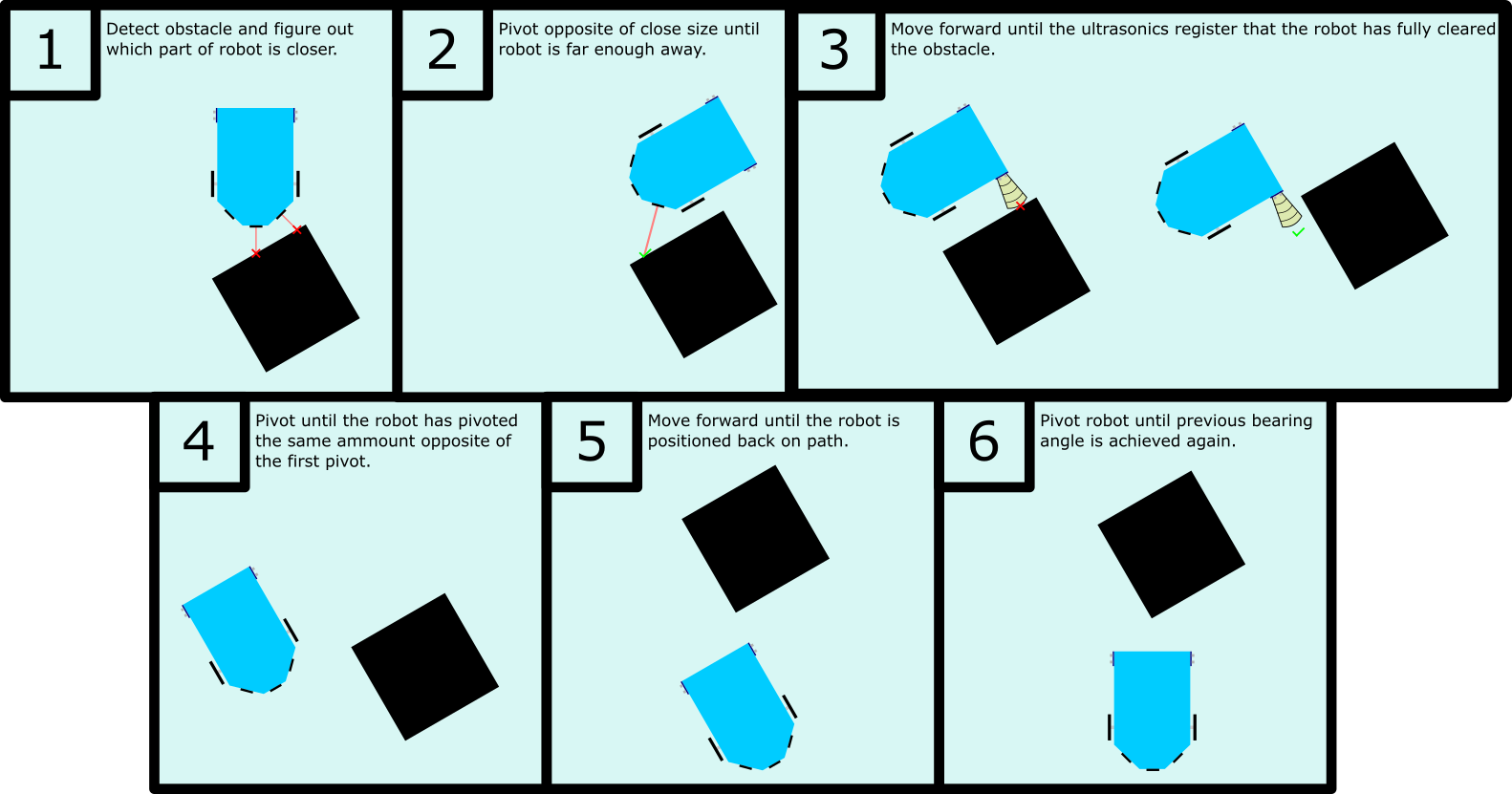
For the initial obstacle detection and marking, IR sensors were used. We added an offset to these sensors, so when the robot moved next to an obstacle, they could be detected and their distances marked. The ultrasonics were used as a check during the avoiding phase of the motion. Since the robot pivots about the front wheel, the robot can risk hitting its rear on an obstacle. Because of this, ultrasonics are used as a check to make sure the whole robot has cleared the obstacle before attempting to turn back.
The IR sensors provide a voltage level as the signal so the ADC is used to translate the voltage to a 12-bit value. This 12-bit value is then brought back into voltage in the C code and the voltage is converted to a distance reading. The ultrasonic sensors work using the eCap functionality of the launchpad. An ultrasonic works by providing timing of when the sound is sent and bounces back to the sensor. This time difference can then be converted to a distance value.
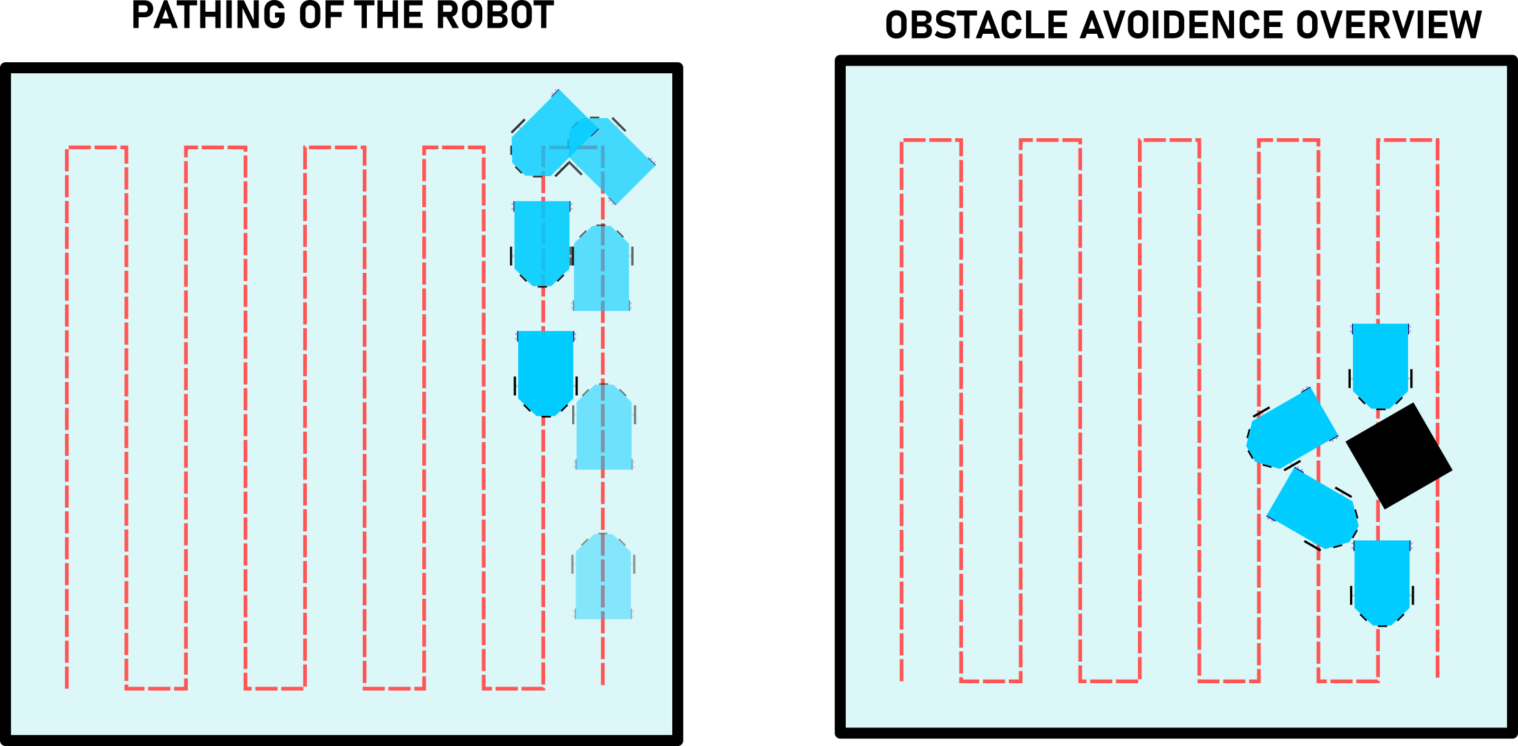
Obstacle Avoidance and PathingSince the overall goal was to create a robot that can map out an area and the obstacles within it, a path needed to be used. For simplicity's sake, a path that simply goes up and down was used based on the geometries of the area of operation. However, as the robot reaches an obstacle it needs to maneuver around, the robot would essentially pivot until it reached an angle that would allow it to move straight without hitting the obstacle. Once the robot would fully clear the obstacle it would pivot back and move to maintain its path to continue mapping out the environment.
Wireless Data TransmissionAnother major part of the project involved the transmission of data to LabView. The Orange Pi was chosen as our secondary board, for its WIFI capability, and for us to get some experience working with it for personal development. The Orange Pi was set up to receive values from the Redboard over UART. Then the Orange Pi would transmit this data over WIFI to LabVIEW using code ran on both the Orange Pi (TCPIP code) and Code Composer. The values that were transmitted included Robot (X, Y) coordinates, Robot Bearing angle, and Obstacle (X, Y) coordinates. Obstacles were detected and identified by the IR sensors to map them out. The FinalProject C file includes the data that was transmitted. The LabVIEW file then processed this data.
To allow a quick setup of the robot during demos, the FinalProject c file was flashed onto the robot, and the TCPIP C file was transferred to the Orange Pi. The Orange Pi used was the Orange Pi Lite, with the Armbian framework.
LabviewIn LabVIEW, we needed to solve 4 tasks. The first was transmitting data to the OrangePI and then receiving data back. Picture 6 shows the TCP subVI that was created to transmit 9 data points and then receive 9 data points back. By using the built-in TCP network blocks this task was rather simple.
The next task was creating an automatic counter which would help automate the rest of the LabVIEW loops (Picture 2). The TCP blocks were activated by a send button being pressed, however, we couldn't sit there clicking that button all day, so we created a while loop which waited 150 ms and incremented a variable. This variable is used to execute all of the loops in this program.
The next task was figuring out how to draw the robot in real-time and making this image move around on a 2D picture plot. Picture 5 shows the Robot drawing VI that was created. First, we created the image of the robot by plotting points on a graph in Desmos and transcribing the points in the blue array. Here we take the robots X, Y, theta values, and the robot image and combine them in a Rotate angle block. This takes the robot data and rotates the image we created so the image matches the robot's true bearing in real life. Next, we added some offsets which just changed the (0,0) origin point to a place we liked and converted feet to pixels. Then, the finalized (X, Y) pixels are entered into a for loop which goes through and updates the robot's drawn pixel position in the plot. Finally, these pixel points are put in a Draw Multiple Lines block which plotted the robot onto a 2D picture.
The final task was attempting to draw the robot's path and the obstacles detected. Since these two tasks were basically attempting the same task of plotting data while updating to plot to include new incoming data without losing previous plotted info, they were combined. This part of the project took the most time to figure out, but once I figured out that shift registers were required, it was pretty simple. Picture 4 shows how we manipulated the robot coordinates and the obstacle coordinates. Here we connected each set of (X, Y) coordinates and used a Draw Point block which would take the coordinate and draw a single point on the 2D picture. These Draw point blocks were connected to an empty 2D Picture block and then connected to a shift register. This shift register was a second 2D Picture block which allowed us to update this picture without losing any data. We added a button that would bypass the first Picture block to stop and start the tracking of data points to help clear some of the clutter on the screen while testing.
Everything was combined inside a Flat sequence which helped distinguish the 3 stages of the program; Connect to Server, Run Program, Disconnect from Server. This program was a lot of fun to make and really showed the potential of LabVIEW for future projects we may have.


Comments