From the start of this assignment, both of us knew we wanted to create an IOT project centered around cats-- we both have a cat which we love. Our initial idea was to make a motion-sensing laser toy for cats. As we started planning the project, however, something dawned on us. Every time we leave the house we worry that a fire could break out while we are not home and that we would return to a house without a cat. We realized that creating an IOT project that could alleviate this fear would be more beneficial, not only to us, but to other pet owners with the same fear. This gave way to the idea of creating an IOT project that will send alerts to the consumer when smoke is detected by a smoke detector.
When smoke is detected by a smoke detector, the Photon wired to the smoke detector receives a signal. This signal is then sent to Pushbullet as well as to the second Photon. Pushbullet will send a notification to the registered cellular device/computer and illuminate the LED on the second Photon.
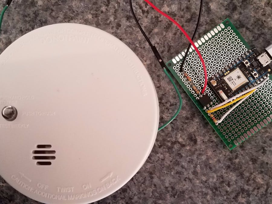
1 / 3 • Completed Circuit Soldered on PCB Board
How?
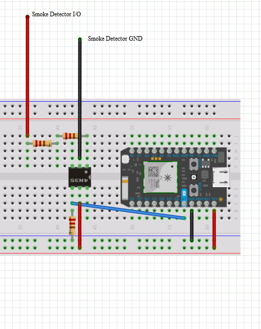
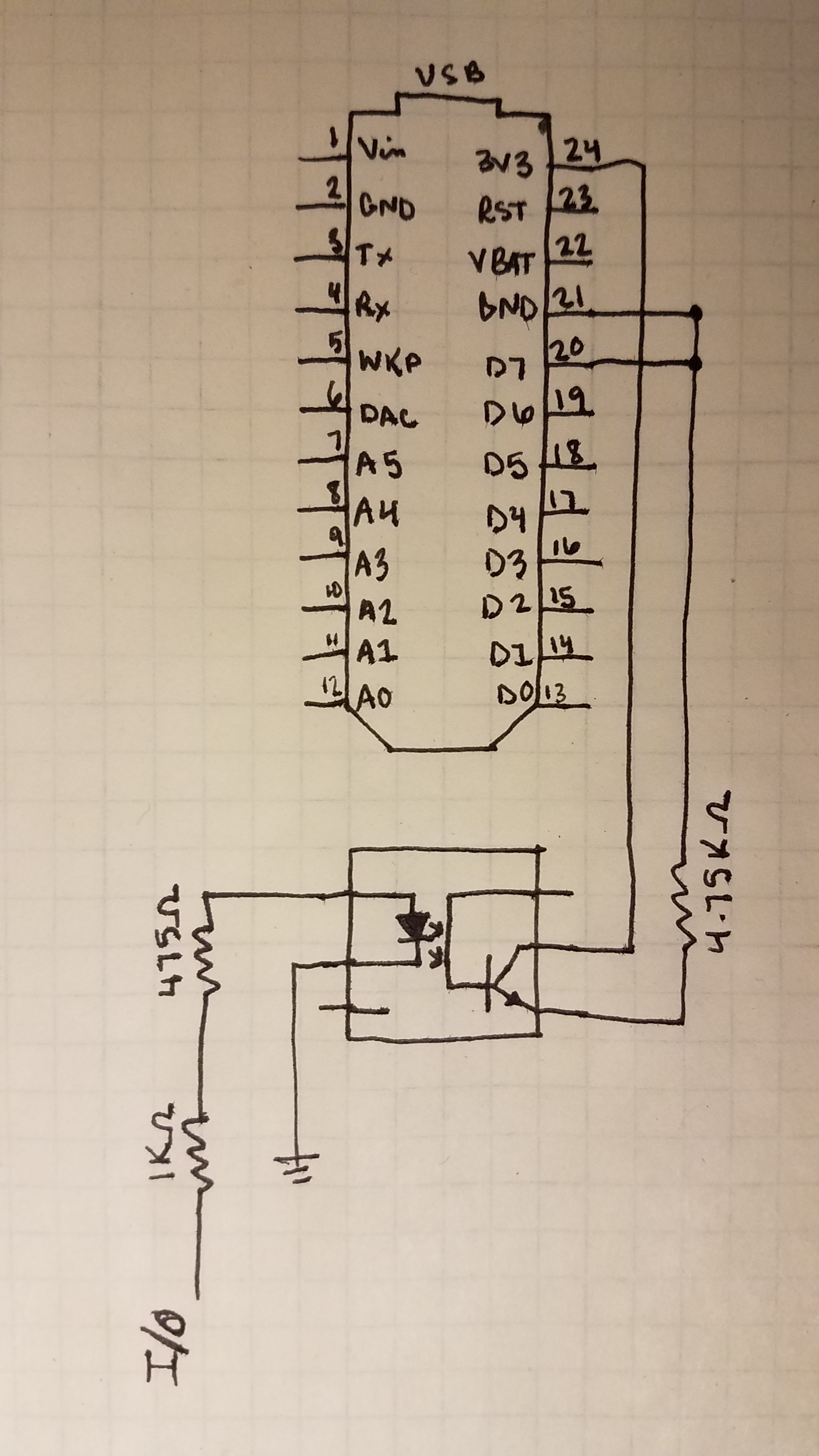
The idea behind the circuit assembly was simple -- connect the I/O pin from the ionization sensor to the photon to alert the D7 pin and publish an event that Pushbullet could read. To do this, the use of an optocoupler was required. An optocoupler transfers an electrical signal between two separate circuits, using light. This is done so that voltages from the separate circuits do not affect each other. The sensors' I/O was connected to pin 1, and its GND to pin 2. The ionization sensors exact pinout could not be obtained, however, the two most popular models had either pin 2 or pin 7 as I/O and each pin was tested to determine which one gave off 9V when the alarm was triggered. Pin 7 was found to be I/O and was connected to pin 1 of the optocoupler via a wire soldered to the sensors pin. Resistors were used to limit current flow into the optocoupler and protect the equipment. Pin 5 was connected to the power supply of the photon, and pin 4 was connected to D7, a resistor, and the GND of the photon.
Pin Diagram for 4N35 Optocoupler
Resistor Calculations
*Above calculations were done while referencing this page.*
There were multiple road bumps and learning curves to using the optocoupler, but once everything was assembled and working properly the results were awesome.
Pushbullet Cellphone Notification
Setting up Pushbullet
Setting up Pushbullet was simple. Create an account on their website, and set up your corresponding devices. It will even alert your Google Chrome Browser. To set up your Photon to talk to Pushbullet, a Webhook should be created. Go to your integrations tab and create a new webhook using the settings below.
Webhook Settings for Photon
The ID will be your own person ID that Pushbullet has given you. This can be found in settings under your Pushbullet account. The event name should be a unique name that no one else would use. The Webhook page will also provide codes for publish/subscribe so that anyone you share the code with can subscribe and alert their photon when the event is published.
Code for Integrating Webhook into IDE
The coolest feature of a Webhook, is that it will provide a graph and log of when the event is published. So there is no need to use an outside graphing source in this case, because only one variable can be monitored. However, if you're like most people and want to see data that can be analyzed, it is simple to set up IFTTT to send data to Google Docs and create a graph. Just download If This Then That, create an account, link the code, and send the data to Google! The code is designed to notify the user after 10 seconds, 1 minute, 5 minutes, 10 minutes, and 15 minutes once the alarm is triggered. This code was adapted from the one found here and its license can be found here.
1 / 2 • Google Docs Graph from IFTTT
So now the project is complete, below is a video showing how it works and some future recommendations.
Code to notify Pushbullet, photon 2, and for graphing
#include"elapsedMillis/elapsedMillis.h"#define SMOKE_READ_INTERVAL 1000#define SMOKE_FIRST_ALARM 10000 //10 seconds#define SMOKE_SECOND_ALARM 60000 //1 minute#define SMOKE_THIRD_ALARM 300000 //5 minutes#define SMOKE_FOURTH_ALARM 600000 //10 minutes#define SMOKE_FIFTH_ALARM 900000 //15 minutes#define SMOKE_NOTIF "SMOKE"elapsedMillissmoke_timer;elapsedMillissmoke_alarm_timer;intsmoke_alarms_array[5]={SMOKE_FIRST_ALARM,SMOKE_SECOND_ALARM,SMOKE_THIRD_ALARM,SMOKE_FOURTH_ALARM,SMOKE_FIFTH_ALARM};intsmoke_alarm_index=0;boolsmoke_detected=false;unsignedlongsmoke_next_alarm=0;intSMOKE_SENSOR=D7;voidsetup(){pinMode(SMOKE_SENSOR,INPUT);RGB.control(true);RGB.brightness(0);delay(1000);RGB.control(false);}voidloop(){smoke_check();if(smoke_detected){smoke_notify_user();}}/******************************************************************************* * Function Name : smoke_check * Description : check smoke sensor at SMOKE_READ_INTERVAL, turns on led on D7 and raises alarm if smoke is detected * Return : 0 *******************************************************************************/intsmoke_check(){if(smoke_timer<SMOKE_READ_INTERVAL){return0;}smoke_timer=0;if(digitalRead(SMOKE_SENSOR)){if(smoke_detected){return0;}smoke_detected=true;smoke_alarm_timer=0;smoke_alarm_index=0;smoke_next_alarm=smoke_alarms_array[0];}else{smoke_detected=false;}return0;}/******************************************************************************* * Function Name : smoke_notify_user * Description : will fire notifications to user at scheduled intervals * Return : 0 *******************************************************************************/intsmoke_notify_user(){if(smoke_alarm_timer<smoke_next_alarm){return0;}smoke_alarm_timer=0;if(smoke_alarm_index<arraySize(smoke_alarms_array)-1){smoke_alarm_index=smoke_alarm_index+1;smoke_next_alarm=smoke_alarms_array[smoke_alarm_index];}Particle.publish("smoke_has_been_detected_27","Smoke detected! Save the cats!",60);Particle.publish("pushbullet","Smoke detected! Save the cats!",60);return0;}
Photon 2 D7 Flash Code
C/C++
Code to flash D7 when smoke alarm goes off
intboardLed=D7;voidsetup(){Particle.subscribe("smoke_has_been_detected_27",flickerled);Serial.begin(230400);pinMode(boardLed,OUTPUT);// Our on-board LED outputParticle.subscribe("smoke_has_been_detected_27",button);}voidflickerled(constchar*event,constchar*data){if(strcmp(data,"Smoke detected! Save the cats!")==0){digitalWrite(boardLed,HIGH);Serial.println("Smoke detected! Save the cats!");}}voidbutton(constchar*event,constchar*data){if(strcmp(data,"buttonpressed")==0){digitalWrite(boardLed,LOW);delay(15000);}}


Comments