

Hardware components | ||||||
_ztBMuBhMHo.jpg?auto=compress%2Cformat&w=48&h=48&fit=fill&bg=ffffff) |
| × | 1 | |||
 |
| × | 4 | |||
 |
| × | 3 | |||
 |
| × | 1 | |||
 |
| × | 1 | |||
Software apps and online services | ||||||
 |
| |||||
Hand tools and fabrication machines | ||||||
 |
| |||||
 |
| |||||
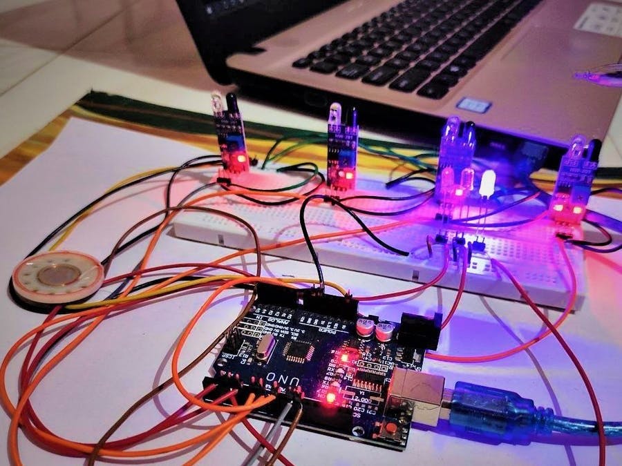
we incorporate all marker Beacon stations (IR Proximity Sensor) and Display (LED bulb and Buzzer). There are three IR Proximity Sensor which are working as a three marker beacon station in our project.
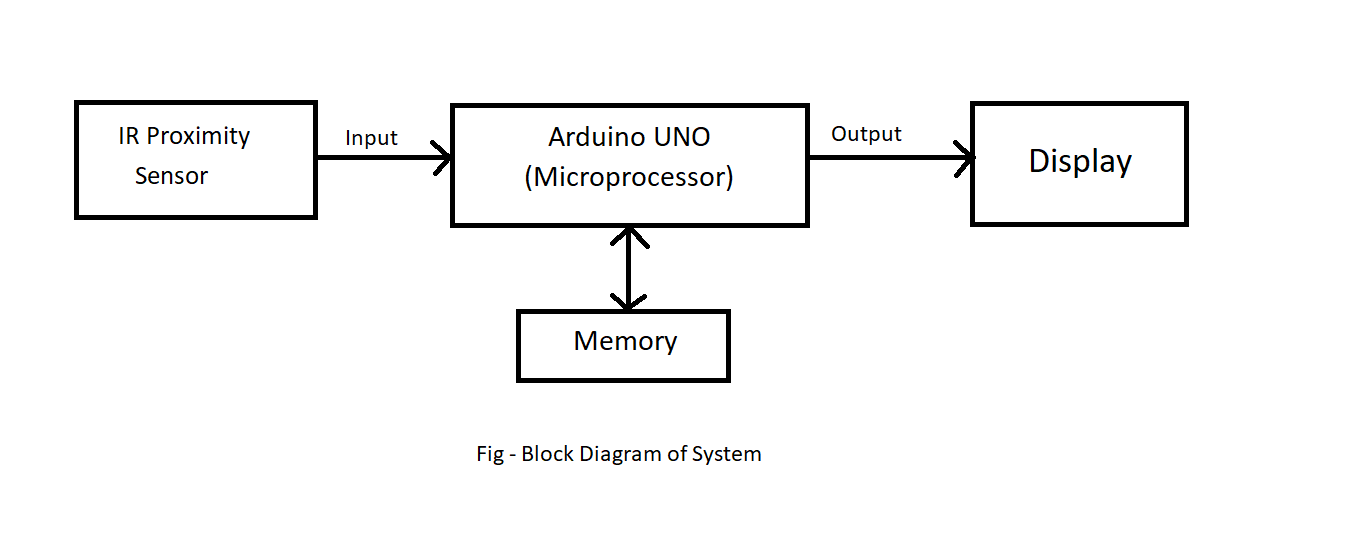
Working principle of IR Proximity Sensor is same as radar. When object is reached within Range of it. It detect the object and gives signal to the Arduino Uno (Microcontroller). When signal reaches to the Arduino UNO. It processes the signal as per program installed in it. Then it runs the display as per the program. Then it runs the display as per the program. On the display of Marker Beacon there are three LED bulbs (Blue, Amber and White) for visual indication and one buzzer for aural indications are install. Display works on the output of Arduino UNO to get correct indication.
In this way landing phase of aircraft is completed but there is one problem during return phase of aircraft there is no any indications require, so that we install fourth sensor named as NRI (Not Return Indication) to resolve this problem. when aircraft reaches on runway then fourth sensor is in the active phase and as we programmed at that time Arduino pauses its working until the aircraft goes outside of all markers range(return to its initial position i.e. top right part of our Model design).
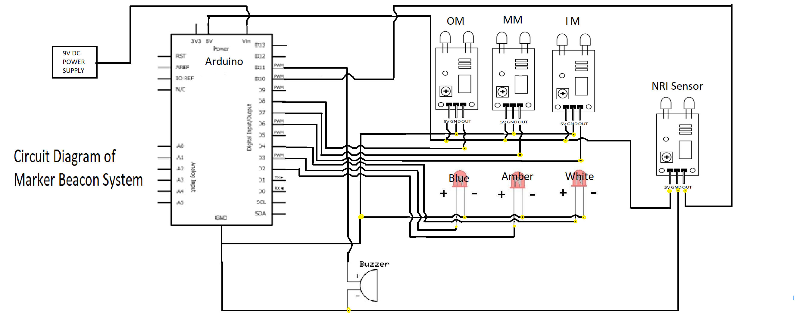
Circuit Diagram
1. Connect OUT of inner marker (Sensor) to Arduino's digital pin 6.
2. Then connect the OUT of middle marker (Sensor) to Arduino's digital pin 7.
3. Same as inner and middle connect the OUT of outer marker (Sensor) to Arduino's digital pin 8
4. Then connect OUT of NRI (No Return Indication sensor) to Arduino's digital pin 10.
5. Connect the GRD i.e. (ground) of all sensors to Arduino's pin ground.
6. Connect VCC of all sensors to Arduino's pin of +5 V.
B) LED's connections:
1. Connect +ve terminal of inner marker (LED) to arduino's digital pin 4.
2. Then connect the +ve terminal of middle marker (LED) to Arduino's digital pin 2.
3. Connect the +ve of outer marker (LED) to Arduino's digital pin 3.
4. After that connect all the -ve outer marker (LED) to Arduino's pin ground.
C) Buzzer connection:
1. Connect one terminal to Arduino's digital pin 11.
1. Connect another terminal to arduino's Pin GRD.
Circuit diagram stanltjx1s


Comments