Use this to shape the servo mount and clearance the dispenser for wiring.
1/4 Drill Bit
Use this to drill the holes in the servo mount for the 1/4-20 fasteners.
8mm End MIll
Use this to counter sink the upper socket head cap screw in the servo mount.
Screwdriver
Box Cutter
Scissor
Super Glue
Foam Board
Story
From the beginning of the IOT-project, our goal was to think if an invention that would benefit pet owners such as ourselves. We started thinking about what problems we were facing and a solution to fix them. After discussing so many ideas, we came to the conclusion that since both of us have pets at home, an automated pet feeder would be a beneficial project. Whenever we go to work or are away on vacation, we always end up paying so much money for pet sitters to feed our pets. We realized that adapting a pet feeder to an IOT application would not only solve our problem but would also benefit other pet owners.
1 / 6
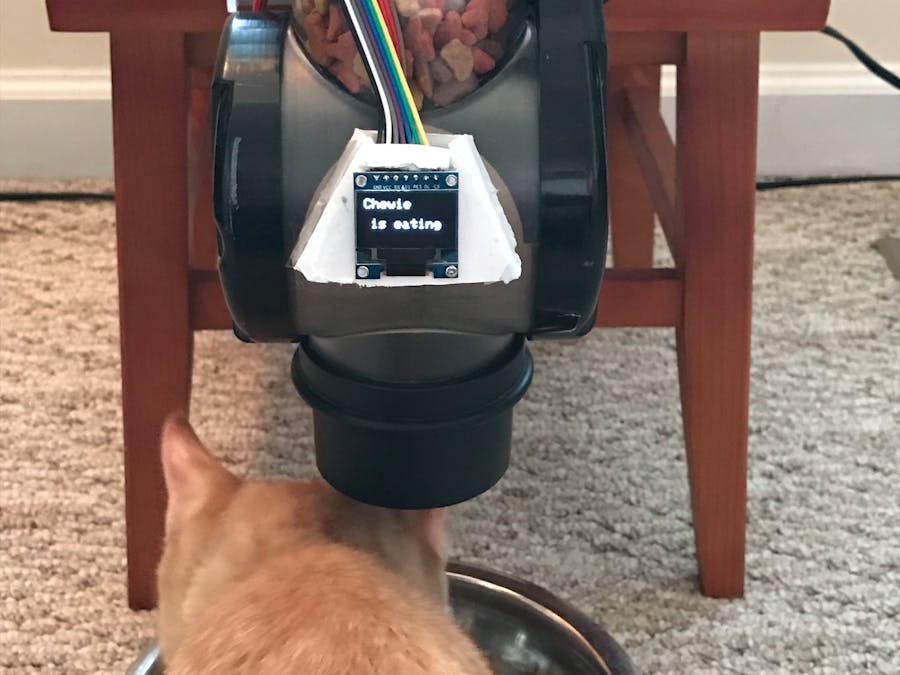
The goal from doing this project was to build an automated pet food dispenser to feed our pets when we are not at home by using an IOT device. The micro-controller chosen for this project was a Particle Photon. Two Particle maker kits were purchased for this project. The mobicle app development website: https://learn.controleverything.com/ was used on our smart phones to activate the Photons on the pet feeder and picture frame. The commands to the pet feeder were also displayed on a shadow box frame. The OLED display was used to provide analytics and information about the habits of the pets. When no activity was present at the dispenser, the display is a clock. When the command is sent to activate the feed lever, the display reads “Chewie was Fed”. A PIR sensor is mounted on the dispenser to detect motion at the food bowl. When the sensor is triggered, the display reads “Chewie is eating”. When the motion sensor is triggered it sends a counted variable to the Things Speak IOT Analytic website and graphs the activity. Things Speak was used to track how many times the pets were fed per day.
1 / 5
The picture frame displayed four states for the pet's food schedule. When the "morning" command was called using the mobicle app (pictured below), the needle in the frame was moved from "skinny" to "healthy". When the "lunch" command was called, the needle moved from "healthy" to "overweight". When the "dinner" command was called the needle moved from "Overweight" to "Fatty". The micro-servo that was supplied in the maker kit from photon was used to move the needle. A small power pack battery was used to power the photon used on the frame circuit.
This video shows all three commands sent to the feeder and their status on the picture frame.
Mobicle was used to send commands to the Photons on the pet feeder and picture frame. The three feed commands move the servo on the pet feeder 180 degrees with an 8ms delay. This command is also sent to the Photon on the picture frame to move the servo to the corresponding position. The OLED also displays the status of the feeder.
1 / 3
The housing for the OLED display also contained the PIR sensor. A box was built to shroud the triggering of the PIR sensor from any heat activity that was not from the pet at the food bowl. This improved the accuracy of the sensor readings.
1 / 5
The first particle Photon was placed on a mini breadboard and was used to control the rotation of the MG958 servo. This servo was responsible for operating the lever on the pet feeder. It is a high torque model servo rated for 5.0V-6.5V. A 6.6V power supply rated at 2500maH was used to supply voltage to the servo. This allowed the maximum rated voltage to be supplied to the servo for maximum torque performance. The photon was used to send the pwm signal from pin D1 to determine the angle displacement and dwell time of the servo. The same power supply was used to power the photon. The current load needed to drive the servo was too high for the photon to handle. An LM317T voltage regulator was used reduce the voltage from 6.6V to 5V. A LM317T calculator from http://www.reuk.co.uk/wordpress/electric-circuit/lm317-voltage-calculator/ was used to determine the resistor combination required to drop the voltage to the desired output. Resistor 1 (R1) was 1,000 ohms and Resistor 2 (R2) was 3,000 ohms. This gave a theoretical voltage of 5.0V. The actual output voltage ended up being 5.4V. This was considered satisfactory because this output voltage was regulated to 3.3V after it reached the photon. The only component driven from the Vin pin was the PIR sensor which still operated with the 5.4V.
1 / 2
An LED was installed to aid in viewing the circuit while it was installed in the pet feeder. A string function called "showcase" was used to turn the LED on and off from the mobicle app. The onboard LED at pin D7 was also used as an indicator light when the motion sensor was triggered.
1 / 2
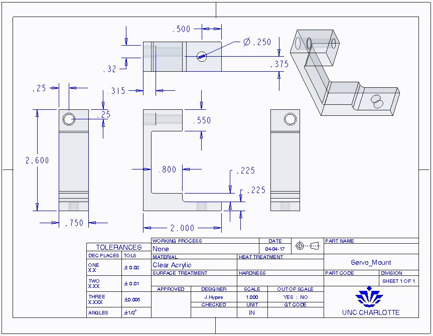
The servo for the pet feeder was mounted to the lower corner of the housing. A small linkage system was installed to move the lever that opened the feed trap. The servo mount was manufactured from a .750 inch thick clear acrylic. It was fastened to the feeder using two 1/4 - 28 socket head cap screws. The servo mount was custom designed for this application. A blueprint for the design is included below.
This video shows the initial testing of the dispenser.
1 / 5
The servo mount was machined on an ENCO milling machine. A 0.500 inch end mill was used to machine the general shape of the mount. A 0.250 inch two flute end mill was used to drill the two installation holes. A 0.315 inch two flute end mill was used to counter sink the fastener wholes.
1 / 2
The same milling machine was used to clearance the housing for the wiring harness to the servo, PIR sensor and OLED display. Plexiglass panels were added to each side to contain the circuit and wiring for the feeder.
1 / 2
Things Speak was used to graph the activity of the motion sensor on the feeder. When the sensor was triggered it increased the number of the variable being sent to cloud. The graph is set to monitor the activity of the sensor over a span of 24 hours. This was published on public channel: https://thingspeak.com/channels/238034
This is a blueprint of the servo mount for the pet feeder.
Schematics
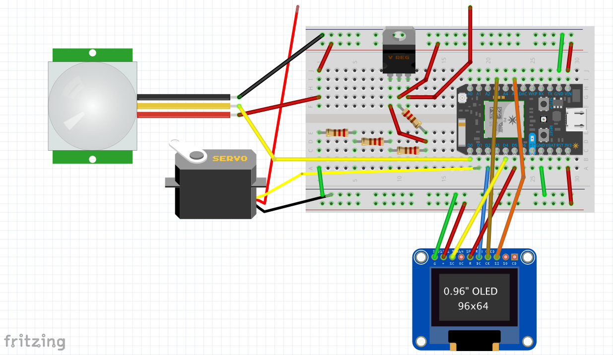
Pet Feeder wiring schematic
This is the wiring schematic used for the circuit in the pet feeder. The servo and open wire going to the LM317 voltage regulator are connected to a 6.6V power supply.
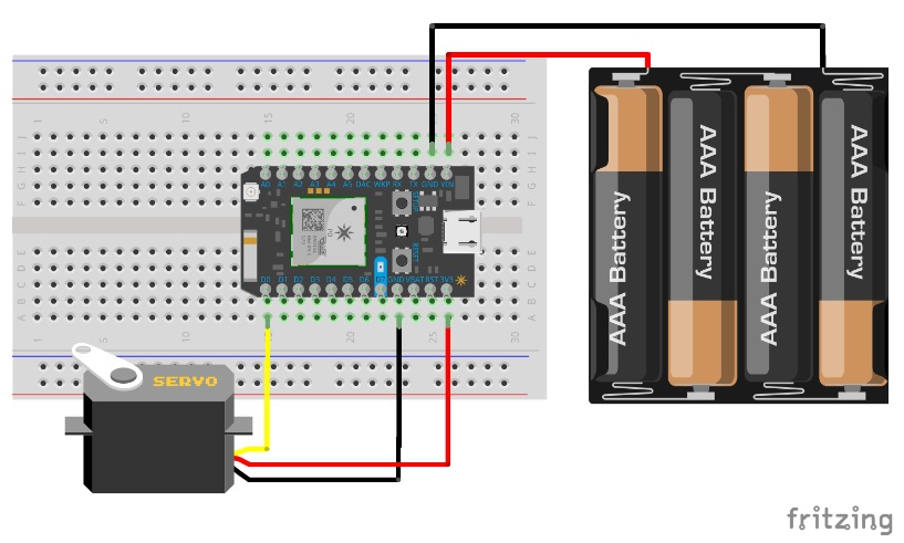
Shadow Box Frame Wiring Schematic
This is the wiring schematic used for the circuit in the Shadow Box Frame to display how many times the pet eats by using a servo motor that moves certain degrees every time the pet eats which changes from Skinny cat to Fatty cat during the day.
This is the code used on the photon that was on the pet feeder. It signals the mg958 servo to actuate the lever on the pet food dispenser and publishes an event to the cloud. It also reads the status of a PIR sensor and publishes a count to thingspeak. It also operates the OLED display.
// This #include statement was automatically added by the Particle IDE.#include<Adafruit_SSD1306.h>Servomyservo;// create servo object to control a servo// a maximum of eight servo objects can be createdintpos=0;// variable to store the servo positionintdisplayTime();//displaytime functionintinputPin=D0;// choose the input pin (for PIR sensor)intledPin=D7;//Onboard LED pinintledPin2=D3;// LED Pin for showcase functionintpirState=LOW;// assuming no motion detectedintval=0;// variable for reading the pin statusintcount=0;//count for the thingspeakwriteallintcalibrateTime=10000;// wait for the calibrationintFeedings=0;//initial feedings #define OLED_DC D2 //Pin out for the OLED Display#define OLED_CS D4 // " " " " " "#define OLED_RESET D5 // " " " " " "Adafruit_SSD1306display(OLED_DC,OLED_RESET,OLED_CS);//OLED Display functionintx,minX;constStringkey="write-key-here";//Thing Speak write keyTimertimer3(15000,updateThingspeak);//Calls Thingspeak every 15000 msvoidsetup(){Particle.function("feed",feedf);// create a function called "feedf" Particle.function("Showcase",Showcasef);// create a function called "Showcasef" timer3.start();//initialize timer3 for thingspeakwrite allmyservo.attach(D1);// attach the servo on the D1 pin to the servo objectmyservo.write(0);// Start from position 0 degreepinMode(ledPin,OUTPUT);//Sets D7 as an outputpinMode(ledPin2,OUTPUT);// Sets showcase LED pin as an outputpinMode(inputPin,INPUT);// declare PIR sensor as input//Particle.subscribe("Feed", myHandler); //Subscribes to operate the OLED displayTime.zone(-5);//Sets the time zone for eastern timeSerial.begin(9600);//Begins the serial printdisplay.begin(SSD1306_SWITCHCAPVCC);display.setTextSize(1);// text size for OLED displaydisplay.setTextColor(WHITE);// text color for OLED displaydisplay.setTextWrap(false);// turn off text wrapping so we can do scrolling}intfeedf(Stringcommand)// Command function for mg958 servo to actuate the feed lever{// be accompanied by a string.if(command=="morning")// if the string is "feed now", feed once.{Particle.publish("Feed","morning");//publishes "Feed" event to the cloudoled();myservo.write(180);// move servo to 180 degreesdigitalWrite(D7,HIGH);// flash the LED (as an indicator)delay(800);// wait 800 msmyservo.write(0);// move servo to 0digitalWrite(D7,LOW);// turn off LEDreturn1;// return a status of "1"}elseif(command=="lunch")// if the string is "feed now", feed once.{Particle.publish("Feed","lunch");//publishes "Feed" event to the cloudoled();myservo.write(180);// move servo to 180 degreesdigitalWrite(D7,HIGH);// flash the LED (as an indicator)delay(800);// wait 800 msmyservo.write(0);// move servo to 0digitalWrite(D7,LOW);// turn off LEDreturn1;// return a status of "1"}elseif(command=="dinner")// if the string is "feed now", feed once.{Particle.publish("Feed","dinner");//publishes "Feed" event to the cloudoled();myservo.write(180);// move servo to 180 degreesdigitalWrite(D7,HIGH);// flash the LED (as an indicator)delay(800);// wait 800 msmyservo.write(0);// move servo to 0digitalWrite(D7,LOW);// turn off LEDreturn1;// return a status of "1"}}intShowcasef(Stringcommand)//Command function for turning the light on/off for viewing the circuit inside once installed in the feeder{if(command=="On"){digitalWrite(ledPin2,HIGH);//Turns on white led on pin D3}elseif(command=="Off"){digitalWrite(ledPin2,LOW);//Turns off whit led on pin D3}}voidloop(){if(calibrated())// if the sensor is calibrated{readTheSensor();// get the data from the sensorreportTheData();// report it out, if the state has changed}else{}}voidreadTheSensor(){//Function for reading the PIR sensorval=digitalRead(inputPin);//Establishes variable for reading the PIR sensor}boolcalibrated(){returnmillis()-calibrateTime>0;}voidreportTheData(){//function for using the PIR sensor input to display on the OLED and publish to the cloudif(val==HIGH){//Setup for the OLED. Splits it onto two linesdisplay.clearDisplay();display.setTextSize(2);display.setTextColor(WHITE);display.setCursor(0,0);//Starts text in upper left hand corner as the datumdisplay.print("Chewie");display.setCursor(10,30);//Moves text over 10 and down 30 from datumdisplay.print("is eating");display.display();if(pirState==LOW){Feedings=Feedings+1;//Iteration adds one Particle.publish("Chewie-is-eating",String(Feedings));//Publishes the string of Feedings to use on the Picture frame and thingspeakpirState=HIGH;setLED(pirState);}}else{staticintlastSecond=61;if(Time.second()!=lastSecond){charmyTimeString[125]="";constintcurrentTime=Time.now();sprintf(myTimeString,"%02d:%02d:%02d",Time.hour(currentTime),Time.minute(currentTime),Time.second(currentTime));//displays time when no activitydisplay.clearDisplay();// clears the screen and bufferdisplay.setTextSize(2);//Text size for OLEDdisplay.setTextColor(WHITE);display.setCursor(12,20);//Moves text over 12 and down 20display.println(myTimeString);display.display();lastSecond=Time.second(currentTime);}if(pirState==HIGH){pirState=LOW;setLED(pirState);}}}voidoled(){//void myHandler(const char *event, const char *data) //Function for displaying on the OLED that the pet feeder was activated//{//if (strcmp(data,"Chewie_was_fed!")==0) {display.clearDisplay();display.setTextSize(2);display.setTextColor(WHITE);display.setCursor(0,0);display.print("Chewie");display.setCursor(10,30);display.print("was fed!");display.display();delay(3000);//Will Display this message for 3000ms before returning to the time//}}voidsetLED(intstate){digitalWrite(ledPin,state);//turns the d7 led on/off based on PIR status}boolupdateThingspeak()//ThingsSpeak code from John McAlpine{count++;Serial.print("Updating Thingspeak:");Serial.print(count);boolsuccess=Particle.publish("thingSpeakWrite_All",+"{ \"1\": \""+String(Feedings)+"\","+"\"k\": \""+key+"\" }",60,PRIVATE);returnsuccess;}
Picture_Frame
Arduino
This is the code used on the picture frame to move the servo.
Servomyservo;// create servo object to control a servo// a maximum of eight servo objects can be createdintpos=0;// variable to store the servo positionintledpin=D7;//Onboard LED pinvoidsetup(){myservo.attach(D1);// attach the servo on the D0 pin to the servo objectmyservo.write(180);// test the servo by moving it to 20Particle.subscribe("Feed",myHandler);//Subacribes to published PIR sensor string and calls muHandler functionpinMode(ledpin,OUTPUT);}voidmyHandler(constchar*event,constchar*data)//Uses the variable from the subscribed event from the PIR sensor{if(strcmp(data,"morning")==0){myservo.write(135);// Mutiplies the string iteration by the number of degrees of movement per picture in the frame plus the inital 20 degreesdigitalWrite(ledpin,HIGH);delay(2000);digitalWrite(ledpin,LOW);}elseif(strcmp(data,"lunch")==0){myservo.write(105);// Mutiplies the string iteration by the number of degrees of movement per picture in the frame plus the inital 20 degreesdigitalWrite(ledpin,HIGH);delay(2000);digitalWrite(ledpin,LOW);}elseif(strcmp(data,"dinner")==0){myservo.write(65);// Mutiplies the string iteration by the number of degrees of movement per picture in the frame plus the inital 20 degreesdigitalWrite(ledpin,HIGH);delay(2000);digitalWrite(ledpin,LOW);}else{}}


Comments