


Hardware components | ||||||
| × | 2 | ||||
| × | 1 | ||||
 |
| × | 1 | |||
If you've ever had any interest in how to control an Individually Programmable LED Strip with a Particle Argon you've come to the right place!
This story includes a COMPLETE guide on how to set up the project and is aimed to leave you with all the information you need to get started with your own Argon controlled Individually Programmable LED Strip!
For this project specifically we will be using 2 Particle Argons, communicating data between each other, in order to display an output on the Individually Programmable LED Strip.
- The FIRST Argon will be individually set up and calibrated as a light-sensor
- The SECOND Argon will be wired to the LED Strip to read incoming data and control the visual output of the Strip
With both of your Particle Argon's set up and connected to the cloud, you're ready to begin!
Set Up*Light Sensor*
Start with the first Argon which is going to be used as a light sensor. This will be done using the materials included with the Argon as well as an additional jumper wire or any working alternative.
Included in the Particle Argon Kit, you should have:
- 1 Single Red LED
- 2 Resistors
- 1 Photo-Resistor
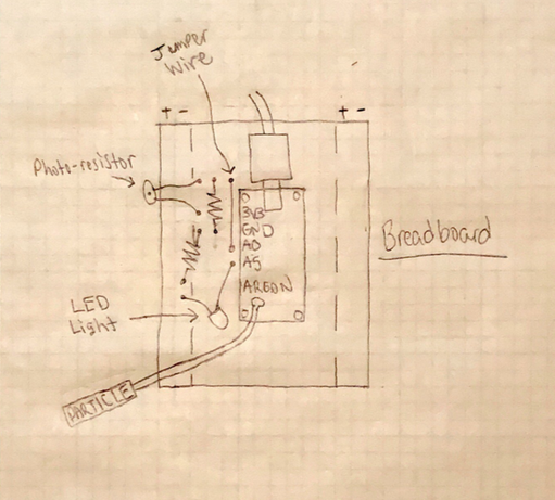
With the Argon disconnected from power you can begin constructing the circuit as shown below in Figure 4. Light Sensor Schematic.
The Red LED will be wired from the A5 pin on the Argon to any ground node on your breadboard. This will be used as an output to display a change in the data input.
The Photo-Resistor will be wired from the A0 pin to any node in the same column but ensuring it is not connected to any of the Argon's other pins as shown in the figure above. This allows the Photo-Resistor to capture light data and display a reading through the LED light or in other words, as the Photo-Resistor detects light the LED will be off but as soon as an absence of light is detected the Red LED will switch on.
2 resistors will be used as buffers in the circuit between the Photo-Resistor and the Red LED. These are wired just as shown in the schematic above and this completes the set up of the light sensor.
*LED Strip + Argon*
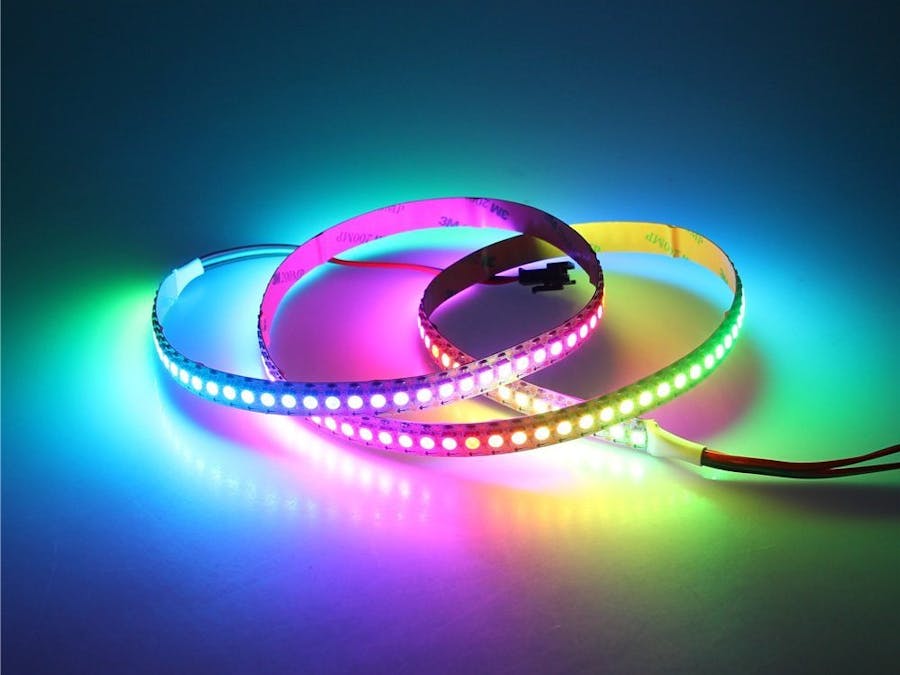
To assemble the next component grab the light strip (WS2812B), the remaining Argon, 2 extra jumper wires and again, make sure the Argon is disconnected from power before proceeding.
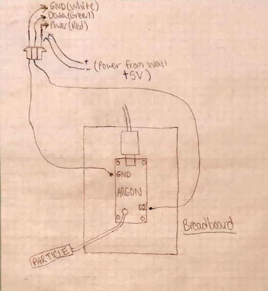
For a simple schematic of this component refer to Figure 6. LED Strip + Argon Schematic shown below.
The strip contains 3 important wires:
Data = Green Colored Wire
Ground = White Colored Wire
Power = Separate Red & White Colored Wire
The green colored data wire on the light strip will be connected from the light strip to the D2 pin on the Argon which will allow us to feed data into the LED's using the connected Argon.
The ground connection, or white colored wire from the light strip will be connected to the GROUND Pin on the Argon.
The red & white colored wires for power, indicating power and ground respectively, have been connected directly from the light strip to a USB Wall Adapter supplying +/- 5 volts.
With both of the components assembled and powered on, all that is left is the code to get the devices behaving correctly in the presence as well as absence of light. Refer to the code we have provided to get the project up and running instantly or feel free to expand on it using the pointers given in the comments to create your own unique patterns or change the way in which the Argons behave.
The Youtube video below provides a quick demonstration of this project in action!
Real Time Data:
The figure below represents the project after running for one full day. A "1" is received when there is no light detected and "0" when it has detected an adequate amount of light.
This was a very exciting experiment with various tools and gadgets that my partner and I have never had the chance to try out until now. Throughout the course of this project we have already managed to gather a handful of new ideas to implement with different IoT devices. We hope this inspires you to create your own project and explore everything thats possible with IoT devices.


Comments