


Hardware components | ||||||
| × | 1 | ||||
| × | 1 | ||||
 |
| × | 1 | |||
| × | 1 | ||||
| × | 1 | ||||
 |
| × | 1 | |||
Software apps and online services | ||||||
 |
| |||||
 |
| |||||
Hand tools and fabrication machines | ||||||
| ||||||
This project is an application that can perform with the digital processing of the signals taken from the Matlab environment, using the Bluetooth module as the medium of information exchange between the computer and the micro controller, for this project work with the PSoC controller 5 The intent of this tutorial is to showcase one of many applications that Matlab offers to work in conjunction with any controller and make wireless applications.
The sections in which this tutorial is developed:
- Construction of the door
- Setting up Bluetooth on the PC
- Programming in Matlab
- Controller Programming
- Schematic
- Video
The construction of the door can vary according to the application you want to perform, since you can do the same project and apply it from a toy door to a real-size door such as a room, modifying only the actuator.
As this project is focused on programming and not on the actuator used, a small door is made to appreciate the operation of the project.
First we make some pieces in table and sticks of bullet as it indicates the following image.
We stuck the motor one corner of the door which takes into account that the motor shaft aligned with the side of the door.
Then we attach a support to the servomotor, making sure that it does not obstruct its movement.
Finally attach the entire structure by attaching this bracket together with the other missing bracket at the base, making sure that no obstruction of the door movement.
To configure the Bluetooth in the PC only with that write in HOME "bluetooth", we open the "bluetooth configuration", activate the bluetooth and match the bluetooth that is using, for this case it is HC-06, the pairing will ask for a Password Which is "0000" or "1234".
It is important to know the name of the device and that after it is placed the same name in a line of code in Matlab which will be explained later.
To start, work on the version of Matlab 2015 to, although the programming is the same in different versions but maybe can change a bit.
First started writing in the Matlab command window the word "guide", which will display an editing window to work in the GUI, click create new and OK.
There will be a window where we will start working the graphical interface, where we will find graphs, buttons, texts, lists, etc.
Now save the document and once saved, it will automatically generate a code in the Matlab edit window with the same name as the guide you just created.
We continue with the editing window and add a graph, two buttons, and 14 signatures as follows.
We will edit each one by double-clicking on each object, doing this displays a new window with the editing options for each object.
In the graph we can change the name, for this case the pond axes2.
For the other objects, double click on each one of them and we deploy the same window, we edit the color, the size of letter and if we want the typeface (normal or bold).
On each object except the graphic, we will assign a name to the object and a label name.
The name that is assigned in the tag part is important and is a name with which that object is called as a variable within the Matlab programming. It does not matter if the name of the object and the name of the label is the same, what if there is to be considered is that two objects can not have the same label name.
For example, set the name and label of the "start" button.
Once understood by the procedure of naming the rest of the objects according to the following table.
When we finish naming the objects, now we have a save the document, and to check that the interface of this moment to our liking, we click the green button (play), if we have made changes and we have not saved. This message will be output and click "YES".
Now we proceed to program each object of the interface. To program each object right click on the interaction objects (buttons, lists, etc). In this case we will program the "start" button, right click and select the option "View CallBack" and there the "CallBack" option.
Clicking here directs us to the Matlab code section generated when we save the guide. And we will write the following code. Global variables are initialized and opened to the computer's Bluetooth port.
We start a "While" for the code you are running all the time until you are prompted.
We recorded a signal and analyzed its frequency in Fourier:
With the following instruction we obtain the fundamental frequency of the signal, in this way we can know which note is playing.
Click here to search the frequency formation and set the frequency ranges that marks each note, after the signs of the vector of the notes we get, which is defined, this vector is the password that is entered by the user manually, This password will be explained later.
When all vectors are equal, it means that the access password is the correct one and an unlock command.
Repeats for all musical notes.
Once the Start button is programmed, follow the Reset button. Just like the Start button, we go to the guide and in the reset button we give right click and select View Call Back and there Call Back.
When clicking on "Call Back" there is no address in the section of code in Matlab that runs this button, there we will write the following code.
The function of this button is for the process and restart the variables.
Now that we have programmed both buttons we initialize the variables for each time we run the program, start the variables in the values we indicate, for this we do not go to the beginning of the code and look where it says
"Function gate_OpeningFcn (hObject, eventdata, handles, varargin)"
Note: my project calls it with the name "puerta" so in its case, leave the name with which you saved it followed by "_OpeningFcn ..."
Finally, we add the configuration of the password selected by the user.
For this we will make a tab in the user interface that is creating, so that the selection is displayed a new window, so we guide them and select the next option.
When you select it, scroll to the next window and select the new menu box.
Then we name the first menu:
Now select this menu and click on the following icon.
You will have to exit the menu (Untitled 2) as shown in the image.
Subsequently we name it and remain as follows.
Then select the submenu that sets (Password) and click on "view"
It will take us to the section of code in Matlab that executes this function and there we will write the following code.
Once finished, when you run the code you can see this menu at the top of the window.
Now create the window where is the interface of the selection of a new password, this window we call "key", if you name it different you must change the name before uiwait by the name with which it is saved.
Now we write in the command window of the word "guide" and create a new guide, then save it with the name "key".
Note: the programs you are generating must go in the same folder so that Matlab can interconnect them.
In the new manual generated, select 4 texts, 3 pop-menu and a button, locating them as follows.
The texts of the names are explained above, following the table below.
Now we double-click the first pop-menu and configure it.
For this object, it is named as it appears in the following figure. We click on the box with the lines that appear to the front of the word.
A small blank window will appear where we will write the notes by pressing "ENTER" so that they are displayed vertically. A space must be left at the beginning by pressing "ENTER" once.
Then we click on the "OK" button and repeat the process for the other two "pop-menu" that are missing. It says exactly the same thing in the "pop-menu" that is missing. Now we will pass a button that gives a double click and typing its "String" and its "Tag" as shown in the following figure.
Now we must program the pop-menu and the button, let's start with the pop-menu. Right click on the first pop-menu and select View Call Back and there Call Back as it was previously returned for other objects.
It will point us to the code section of the new window you just created, which ejects this object.
There we will write the following code.
Then we do the same for the second "pop-menu" in which we will write the following code.
And then we do the same for the third "pop-menu":
Now we will program the button, right click and select "View Call Back" and then "Call Back". There we will write the following code.
Finally we go to the beginning of the code where we initialize the variables, for this we look for where it says "function clave_OpeningFcn (hObject, eventdata, handles, varargin)". And then we initialize the variables where indicated in the following image.
Done this already finished the programming in Matlab.
Section 4: Programming the MicrocontrollerThe function of the microphone controller in this project is the command to open or close the door, so you are always reading the data that we sent from the computer which will be a "d" to unlock or a "b" to lock.
We open a new project and select PSoC 5 and the reference of the card, which is printed on the micro controller.
In the following image are all the programmable blocks that PSoC handles
First we have to add a UART block that is in the communications folder, and we configure it the way the way
Next we add a block of PWM (it is in the folder "Digital"), a block of clock "Clock" (it is in the folder "system") and configurations of the following way.
It is important that the period be of 20 ms, since the servomotors that are used to handle this frequency, in case of a different servomotor to the adjustment this parameter by modifying the value of the clock block "Clock" or the value of the period of the pwm "Period".
Now double click on "main" to write the code and double click on "puerta.cydwr" to select the pines.
Note: the project will save it with the name of "puerta"
To configure the pins, the following window will appear.
Select the pines as follows.
- Pin_1 on pin P0 [1]
- Rx_1 on pin P12 [6]
- Tx_1 on pin P12 [7]
Now we go to the "main" window and write the following code.
Note: in case the program the servomotor the logic of the door opening is inverted, only change the command line.
PWM_WriteCompare (183) over the PWM_WriteCompare line (170)
And we also changed the line:
PWM_WriteCompare (170) over the PWM_WriteCompare line (183)
That is to say, it is only to invest those two values. Finally compiled by clicking the next button.
And it should not generate any errors.
This way you are already receiving the instructions of locking and unlocking the door to be executed. You only need to burn the program in PSoC 5, which will only connect the card directly to the PC and we will click on the next button.
Now it is only necessary to rehearse the entire program as a whole.
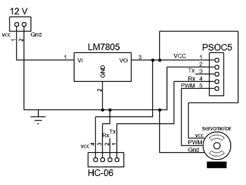
Section 5: SchematicThe circuit assembly consists of a servomotor and a Bluetooth module, so it is not complex to perform.
- The bluetooth Tx pin with Rx pin going on PSoC (pin P12 [7]).
- The output servo motors are configured in the PSoC (pin P0 [1]).


Comments