


Hardware components | ||||||
| × | 1 | ||||
 |
| × | 1 | |||
 |
| × | 1 | |||
 |
| × | 1 | |||
| × | 1 | ||||
| × | 1 | ||||
| × | 1 | ||||
| × | 1 | ||||
| × | 2 | ||||
 |
| × | 1 | |||
| × | 1 | ||||
| × | 1 | ||||
 |
| × | 1 | |||
 |
| × | 1 | |||
 |
| × | 1 | |||
| × | 1 | ||||
 |
| × | 1 | |||
 |
| × | 1 | |||
 |
| × | 1 | |||
Software apps and online services | ||||||
| ||||||
| ||||||
 |
| |||||
_4YUDWziWQ8.png?auto=compress%2Cformat&w=48&h=48&fit=fill&bg=ffffff) |
| |||||
Hand tools and fabrication machines | ||||||
 |
| |||||
 |
| |||||
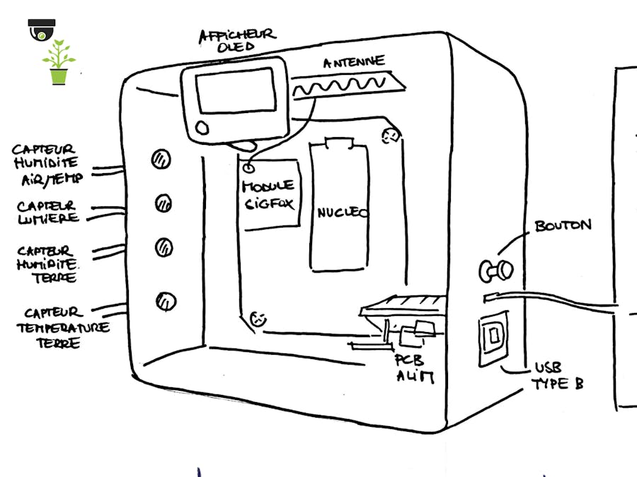
During our studies at Polytech Sorbonne, a agri-food teacher needed a device to follow one of his experiment with his class. It consisted in measuring the difference between a plantation of wheat, a plantation of clover and a plantation of wheat and clover. The solution we proposed had to measure parameters of the planting, send them on Internet and be autonomous.
Coding the sensors to collect dataFloor humidity
Sensor : Grove 101020008
Connection :
- GND (black wire) to GND
- VCC (red wire) to 3.3 V
- Analog (blue wire) to A1
Code :
#ifdef FLOOR_HUMIDITY
int fct_humidity_sol(void)
{
    float val_min = 0.377;
    float val_max = 0.772;
    float mesure, mesure_etalonnee;
    mesure = capteur_humidity_sol.read();
    mesure_etalonnee = (1-((mesure - val_min)/(val_max - val_min)))*100;
    #ifdef DEBUG
    pc.printf("hum sol: %d\n\r", (int) mesure_etalonnee);
    #endif
    return (int) mesure_etalonnee;
}
#endif
This sensor returns a voltage, so you just need to measure it on a ADC pin.
val_min is the return value when the sensor is in water, val_max when the sensor is in the air (you can also measure them by your own).
capteur_humidity_soil was declare earlier as an AnalogIn(A1).
Floor temperature
Sensor : DS18B20
Connection :
- GND (black wire) to GND
- VCC (red wire) to 3.3 V
- Digital (yellow wire) to D3
Code :
#ifdef FLOOR_TEMPERATURE
void temp_sol()
{
    int result = 0;
    ds1820.begin();
    ds1820.startConversion();
    wait(1.0);
    result = ds1820.read(temperature_sol);
    #ifdef DEBUG
    switch (result) {
        case 0:
            pc.printf("temp = %3.1f C\r\n", temperature_sol);
        break;
        case 1:
            pc.printf("no sensor present\n\r");
        break;
        case 2:
            pc.printf("CRC error\r\n");
    }
    #endif
}
#endif
startConversion() function starts temperature conversion from analog to digital.
The debug part allows you to know if the sensor is working correctly, using a serial connection.
The read function of ds1820 writes the value of the temperature in the variable given in parameters.
Air humidity and temperature
Sensor : DHT22
Connection :
- GNG (or -) to GND
- VCC (or +) to 3.3 V
- OUT (or DAT) to digital pin D11
Code :
#ifdef AIR_PARAMETERS_DHT22
void air_temp_hum(){
    int err;
    wait(1);
    do{
        err = dht_sensor.readData();
        wait(1);
    }while(err != 0);
    temperature_air = dht_sensor.ReadTemperature(CELCIUS);
    humidity_air = dht_sensor.ReadHumidity();
}
#endif
temperature_air and humidity_air are global variables, in which the values are stored.
This code performs a measurement as long as an error is returned by the sensor.
Light intensity and RGB distribution of the light spectrum
Sensor : ADA1334
Connections :
- GND to GND
- 3v3 to 3.3 V
- SDA to D12 (i2c)
- SCL to A6 (i2c)
- (LED to GND)
Code :
#ifdef RGB
void fct_RGB(void)
{
    int somme;
    uint16_t clear, red, green, blue;
    if (!RGBsens.begin())
    {
        #ifdef DEBUG
        pc.printf("No TCS34725 found ... check your connections");
        #endif
        lum = 30000;
        /* while (1); // halt! */
    }
    RGBsens.getRawData(&red, &green, &blue, &clear);
    somme = red + green + blue;
    /* pr, pg, pb are percentages of red, green and blue in the light */
    pr = red*100/somme;
    pg = green*100/somme;
    pb = blue*100/somme;
    */ intensity calculation in lux */
    lum = (unsigned short) RGBsens.calculateLux(red, green, blue);

    /* To view data on a terminal */
    #ifdef DEBUG
    pc.printf("luminosite : %d \n\r", lum);
    pc.printf("rouge:%d vert:%d bleu:%d \n\r", pr, pg, pb);
    #endif
}
#endif
The main code
The objective is to have a code for reading and sending data on a regular basis.
int main(){
    #ifdef INTERRUPTEUR
    /* To cut off the supply of sensors */
    interrupteur = 1;
    #endif
    #ifdef OLED
    */ Interruption to wake the screen up with the button */
    bouton.rise(interruption_bouton);
    initOLED();
    #endif
    while(1) {
        if(flag_readData)
            readData();        /* Reading the data */
        flag_readData = true;
        #ifndef DEEPSLEEP
        wait(DUREE_OFF);
        #endif
        #ifdef DEEPSLEEP
        /* If the screen is on, wait before turning it off */
        if(oled_on){
            wait(DUREE_ECRAN_ON);
            turnOffScreen();
            flag_readData = false;
        }
        else{
            /* Going to sleep for predefined time */
            WakeUp::set_ms(DUREE_OFF*1000);
            deepsleep();
        }
    #endif
    }
}Format and send data over the sigfox network
We decided to use the LPWAN (Low Power Wide Area Network) Sigfox to send the data to the internet. This is a relevant choice because the product has to be autonomous in energy.
The Sigfox network allows us to send 140 messages per day, and 12 bytes per message. In order to send all the monitored data, we organized our variables not to exceed 12 bytes :
For the air and soil temperature, the data are collected in float then multiplied by 10 and casted in shorts.
The code to use the Sigfox module :
#ifdef SIGFOX
void sendDataSigfox(void){
    #ifdef DEBUG
    pc.printf("Sending Data to Sigfox \n\r");
    #endif
    short tempSol_short, tempAir_short;

    tempSol_short = (short)(temperature_sol*10);
    tempAir_short = (short)(temperature_air*10);

    wisol.printf("AT$SF=%04x%02x%04x%02x%04x%02x%02x%02x%02x\r\n",tempSol_short, humidity_sol, tempAir_short, humidity_air, lum, pr, pg, pb, vBat);
}
#endif
The Sigfox backend allows us to see messages sent by the device :
Setup a Callback to the ubidots platform
One of the functionality of the Sigfox backend is to provide tools to do callbacks. We chose to make callbacks to Ubidots education to display the collected data.
To do so, once connected to the Sigfox backend, you have to click on "device" and then on the "device type" of your device.
On the left menu, choose "Callbacks" and "edit". On this new page, you will have to inquire some information about your Ubidots dashboard, the size of your variables and a JSON code for the body.
{
    "temperatureFloor" : {"value":"{customData#temperatureFloor}"},
    "humidityFloor" : {"value":"{customData#humidityFloor}"},
    "temperatureAir" : {"value":"{customData#temperatureAir}"},
    "humidityAir" : {"value":"{customData#humidityAir}"},
    "lux" : {"value" :"{customData#lux}"},
    "Rouge" : {"value" :"{customData#rouge}"},
    "Vert" : {"value" :"{customData#vert}"},
    "Bleu" : {"value" :"{customData#bleu}"},
    "Battery_lvl" : {"value" :"{customData#vBat}"}
}
You can now see your data on Ubidots and configure your dashboard as you wish.
Designing of a power supply stage
First of all, in order to supply the microcontroller and the sensors with 3.3 V, we designed a power supply stage with KiCad.
It includes JST connectors for solar panel and battery, an USB type B connector to charge the battery, and a DCDC to have 3.3 V to power the system. It also includes a MCP73831 to manage the charge and discharge of the battery.
Setting up the deep sleep mode and wake up
To reduce the power consumption when the system is waiting between 2 measurements (most of the time), we used the WakeUp library and the deepSleep function of Mbed.
#include "WakeUp.h"

WakeUp::set_ms(DUREE_OFF*1000);
deepsleep();
Adding of a voltage controlled switch
After reading and sending data to the Sigfox network, during the sleep period, the sensors and the Sigfox module were still consuming too much current. So we added a voltage controlled switch to cut off the supply of all the sensors and the Sigfox module.
It is controlled by digital pin D11. The switch is turned on when the microcontroller is awake in order to perform the reading, and turned off before the microcontroller will go into sleep mode.
#ifdef INTERRUPTEUR
DigitalOut interrupteur(D11);
#endifRemoving the solder bridges
On the STM32L432K board, there are solder bridges you can remove to improve the power consumption (you can learn more about solder bridges here). Thanks to our 3.3V supply, we can remove the solder bridges SB9 and SB14 wich are powering the STLINK.
/!\ If you remove solder bridges SB9 and S14 you will lower your power consumption, but you won't be able to reprogram your microcontroller !
With all these improvements for energy consumption, we have reached an average consumption of 4 mA against 80 mA without. This low consumption is compensated by the contribution of the solar panel, the system is therefore autonomous in energy.
How to reuse our codeLibraries needed
To use the sensors, we used librairies. All these librairies are available on Mbed. You can also find all of them on our Mbed project repository.
#include "DS1820.h"
#include "DHT.h"
#include "Adafruit_TCS34725.h"
#include "ssd1306.h"
#include "standard_font.h"
#include "bold_font.h"
#include "WakeUp.h"
Using define.hh file
Our code is very flexible. Indeed, you can decide to use or not a feature just by commenting one (ore more) line of the define.hh file.
define.hh :
#pragma once
/* #define DEBUG */
#define SIGFOX
#define FLOOR_TEMPERATURE
#define FLOOR_HUMIDITY
#define RGB
#define OLED
#define INTERRUPTEUR
#define AIR_PARAMETERS_DHT22
#define DEEPSLEEP
#define BATTERY_LVL
DEBUG is used to display information about what the program is doing on a terminal, using a serial connection.
SIGFOX allows you to send the collected data to the internet using the Sigfox network. Commenting this line will disable the Sigfox module.
FLOOR_TEMPERATURE, FLOOR_HUMIDITY, AIR_PARAMETERS_DHT22, RGB match the different sensors. You can comment one of these lines if you don't want to use one or many sensors.
OLED allows you to display last measured values on the OLED screen when you push the red button (see more below).
DEEP_SLEEP enables the deepSleep mode to reduce power consumption. If you comment this line, the microcontroller will be in a "wait state" between two mesures and it will consume more energy.
BATTERY_LVL : if this feature is activated, the battery voltage will be sent and displayed on the Ubidots dashboard.
INTERRUPTEUR : this allows the voltage controlled switch to cut off the power supply of sensors and Sigfox module in order to reduce the power consumption.
One more thingButton and OLED screen for last measure
To make our product more "user-friendly", we wanted to add something that allows the users to see the latest measured data without going on the internet.
So we added an Adafruit OLED screen.
First of all, when the device is turned on, an initialization function is called.
#ifdef OLED
void initOLED(void){
    oled.on();
    oled.initialise();
    oled.clear();
    oled.set_contrast(255);
    oled.set_font(bold_font, 8);
    oled.printf("================");
    oled.printf("\n\r");
    oled.printf("      2PA2S");
    oled.printf("\n\r\n\r");
    oled.printf("FRAYSSE GERMAIN");
    oled.printf("\n\r\n\r");
    oled.printf("   DUPLESSIS");
    oled.printf("\n\r");
    oled.printf("================");
    oled.update();
    wait(10);
    oled.clear();
    oled.update();
    oled.sleep();
}
#endif
Then, if the user presses the red button, another function is called to display the latest measured data :
#ifdef OLED
void oledData(void){
    #ifdef DEBUG
    pc.printf("Displaying Data\r\n");
    #endif
    if(!oled_on){
        oled.wake();
        oled.clear();
        oled_on = 1;
    }
    oled.clear();
    oled.printf("AIR T : %.1f", temperature_air);
    oled.printf("\n\r");
    oled.printf("AIR H : %d", humidity_air);
    oled.printf("\n\r\n\r");
    oled.printf("FLOOR T : %.1f", temperature_sol);
    oled.printf("\n\r");
    oled.printf("FLOOR H : %d", humidity_sol);
    oled.printf("\n\r\n\r");
    oled.printf("Light : %d", lum);
    oled.printf("\n\r");
    oled.printf("R %d G %d B %d", pr, pg, pb);
    oled.update();
}
#endif
Let's talk about this famous red push button.
We connected this button to the pin A2. When it is pushed, an external interrupt is generated, and a function is called to turn on the screen and display data.
void interruption_bouton(){
    bouton.disable_irq();
    #ifdef DEBUG
    pc.printf("Button interrupt\r\n");
    #endif
    #ifdef OLED
    if(!oled_on){
        oledData();
    }
    #endif
    bouton.enable_irq();
}
Another function is called when the duration "DUREE_ECRAN_ON" is over:
#ifdef OLED
void turnOffScreen(void){
    #ifdef DEBUG
    pc.printf("Turning off screen \n\r");
    #endif
    oled_on = 0;
    oled.sleep();
}
#endif
In order to avoid the rebound effect with the push button, we made this small circuit :
This is what the final product looks like :


_Ujn5WoVOOu.png?auto=compress%2Cformat&w=40&h=40&fit=fillmax&bg=fff&dpr=2)


Comments