


Hardware components | ||||||
 |
| × | 1 | |||
 |
| × | 1 | |||
 |
| × | 1 | |||
| × | 1 | ||||
Software apps and online services | ||||||
 |
| |||||
| ||||||
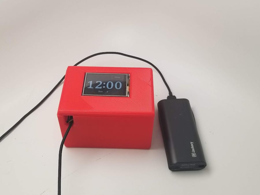
For the final project in Embedded Systems, we constructed a prototype smart watch. The prototype watch had programmable time and date shown on a touch screen display, Bluetooth communication with a smartphone, and a programmable alarm with an alarm sound and vibration.
Project Scope
The team integrated several modules into the smart watch design: power supply, display, bluetooth, haptic feedback, and an alarm. The watch design used existing modules to solve specific design challenges and limit the scope to achievable goals within the timeframe of the semester.
The touch screen display had an interface for programming some functionality. The interface simplified working with the display and allowed the team to focus on communicating with the display using the UART protocol.
The Bluetooth module worked with an existing app to communicate with smartphones. The app simplified the task of connecting to bluetooth and allowed our team to focus on programming the UART driver to communicate between the microcontroller and the Bluetooth module.
Our team wrote the UART driver used in the design. Several examples of existing drivers provided guidance for writing the driver. The documentation for the MSP432 microcontroller also described the UART peripheral and which registers were involved in writing a UART driver.
Our design used one driver modified to be used with the display and the Bluetooth module. Our current strategy will be to write one driver that can be modified to be used twice with each of the two devices using UART: the display and the Bluetooth module.
The haptic feedback portion of the design used programming and hardware we had previously written and built. As a result, the challenge of incorporating haptic feedback (i.e. vibration) into the smart watch was limited to integrating this working module into the design. Our team previously worked with an I2C driver for the haptic driver and attached LRA. This existing I2C driver was modified to fit into the overall design.
The alarm (i.e. buzzer) we opted to use was a through-hole component. Incorporating a through-hole buzzer was simpler than using a surface mount component according to instructor Blum. We used the buzzer with a GPIO pin on the microcontroller. The team had worked with GPIO pins previously and used this experience to incorporate the alarm.
We fabricated a customer printed circuit board (PCB) for the watch. The PCB served as a shield compatible with the MSP432 development board. The shield included traces and pins for connecting components to the MSP432. Previously we had fabricated several PCBs to support the DRV2605L haptic driver and a linear resonant actuator (LRA). The haptic driver and its required resistors and capacitors were surface mounted to the shield. The PCB schematic and board layout are included later in this report.
Project Changes and Challenges
Through the process of working on this project, we encountered a number of challenges that required us to change the original scope. One of the main challenges was with decoding a bluetooth transmission to set the RTC module properly. Originally, we had set out to just transmit simple hex values over bluetooth, which represented the exact numbers that we wanted to put in the registers for configuring and setting the RTC. This led to some difficulties with testing the bluetooth and RTC modules because the strings of values being sent over bluetooth weren’t very readable. To make this easier, as well as get functionality closer to an actual smart watch, we changed this to decode UTF-8 strings sent over bluetooth. This introduced new challenges in changing UTF-8 numbers to binary coded decimal for the RTC registers.
Additionally, the screen presented a lot of challenges to create the functionality we wanted. There was very little documentation on how to use the provided editor for the screen, as well as the UART communication that the screen used. This required a lot of debugging and use of the Logic Analyzer to figure out how the screen function.
With the unexpected difficulties and changed functionalities for the screen and bluetooth, we changed the scope of our project to no longer have a low power mode for conserving battery life. We were able to test the project with our portable power supply, and had no issues regarding the project drawing too much power. With this, we felt comfortable cutting out the low power mode as all of the other components of our project would have needed to be changed to incorporate the low power mode.
We also ended up using the RTC alarm registers to set the timer, instead of creating a separate timing module. This introduced new difficulties in understanding how to set a timer differently than an alarm, and to set it for the proper time. The change was made to simplify the bluetooth decoding functionality, and because we had not completed all of the calculations needed for proper configuration of the Timer32 module, so switching was easy.
Functional Block Diagram
Pin Mapping
PCB
We created a custom PCB to act as a shield between the MSP432 and our components. This PCB also holds the haptic driver, LRA, and piezo buzzer that we used, as they're all surface mount or through hole components that we put directly on the board. The board connects to the MSP432 through rows of pins that correspond directly to the pins on the breakout board we used for the MSP432. The external components we used connect to the board through header pins as well, however in future iterations it could all be made smaller by putting everything on one PCB. The schematic and board can be seen below.
Project Requirements
To define the goals of the design, our team wrote the following requirements.
Functional Requirements:
- Includes a clock based on real time increments (i.e. seconds, minutes, and hours) programmable via bluetooth
- Includes a programmable alarm
- Includes a programmable timer
- Includes a visual display that shows current time
- Includes a piezo type buzzer to provide an alarm sound
- Includes a haptic driver and attached actuator to provide alarm vibration
- Includes a custom PCB that will connect to the MSP to provide connections to components (i.e. resistors, capacitors, Bluetooth module, and display)
- UART communication for the bluetooth module and screen
- I2C communication for the DRV2605L
- Low power mode to conserve battery life removed after better understanding the requirements of other aspects and difficulties of implementation
Future Project
This project turned out really well and taught us all a great deal about embedded systems. Although the end product wasn't exactly a small, wearable smartwatch with all the original features we had planned, we're very happy with what we learned and created. This project also gives a lot of room for improvement and iteration in the future, should we want to revisit it. It wouldn't be too hard to condense everything onto one PCB, including the MSP432 instead of using the breakout board. Additionally, we could look deeper into bluetooth and wireless functionality to make the hardware even smaller by creating an antenna on our PCB. On the feature side of things, we could revisit the idea of a low power mode to conserve battery life, as well as implementing more information on the screen, such as if an alarm is set. Overall, this project was an incredible learning experience, and gave us all a good introduction, while providing room to continue learning.


_3u05Tpwasz.png?auto=compress%2Cformat&w=40&h=40&fit=fillmax&bg=fff&dpr=2)


Comments