


Hardware components | ||||||
| × | 1 | ||||
| × | 1 | ||||
| × | 1 | ||||
 |
| × | 1 | |||
Software apps and online services | ||||||
 |
| |||||
Hand tools and fabrication machines | ||||||
| ||||||
 |
| |||||
For photographers who require mobile lighting for both day and night settings, the RCD|LED (Remote Controlled Dimming LED) is a rebuild of a retail high-power LED lighting panel that converts the panel from analog to digital, greatly increasing dynamic range and adding wireless remote control.
Unlike panels that are far too bright for long exposure night photography, use imprecise analog controls, and require physical access to the panel to change settings, the RCD|LED provides:
- an 11.5-stop range of light from extremely dim to full brightness
- precise digital control in 1/2 stop increments (up/down and specific number of f-stops)
- complete control from any web browser over WiFi
- a WiFi access point for wireless control in any location
All the source files are located in the RCD|LED BitBucket project repository. This repo has the following folders (use of the source files is explained below):
- LEDPanelDimmer: C++ source files
- MacAddress: utility to determine ESP8266 MAC address
- PCB Frame: STL file for the PCB holder
- Photos: project photos
- docs: supporting documents, including the Bill of Materials (BOM)
- eagle: control board schematics, board layout, and parts library
This project came about for a very practical reason. We were leading a night sky photography workshop, and the goal was to light foreground objects while getting a dramatic shot of the night sky in a remote area. The problem we quickly ran into was that the panels put our far too much light. We compensated for this by using filters and multiple sheets of vellum paper, but we agreed there must be a way to electronically limit the light output and simultaneously gain more precise control. Moreover, the lights were located fairly far away from the shooting location, with a lot of cacti and brush in the way as well, making exposure adjustments time consuming and tedious.
We had three different panels available: a Neewer CN-216, a Neewer CN-160, and a Yongnuo YN 1410. (This project will describe how to modify the Neewer panels only, but the board and firmware will support the Yongnuo also.)
We took them apart and analyzed the circuitry, concluding that the only way to meet our goals of would be to design a new circuit from scratch using a microcontroller. A friend pointed us to an article on PWM control for high power LED circuits, and a prototype based on an ATTiny provided our proof of concept.
From the prototype, we learned that the dimming provided by typical PWM using 8 bits, as available on the ATTiny or Arduino Uno, did not dim these panels sufficiently for night sky photography settings. Measurements indicated that we needed to be able to dim any panel down to about .5 candela per square meter! We needed a microcontroller with a 10 to 12 bit PWM resolution to achieve this low a light level. The ESP8266 used as a standalone microcontroller/SoC met all these requirements as well as providing the WiFi access point we needed for remote control.
The software is composed of three main elements: PWM control of the LED panel, the HTTP WiFi server, and the HTML code for the user interface. We discarded all of the existing electronics and controls, keeping only the enclosure, LED panel, and battery.
Electronics[Note: a complete Bill of Materials (BOM) is in the BitBucket repo.]
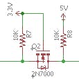
Working out the circuit proved straightforward. We had to make sure to select components that would support the full power draw. Each of the three panels had unique characteristics that had to be handled through component selection. The power required meant some large TO-220 packages for the voltage regulator and MOSFET power transistor plus a 2W resistor. The ESP8266 ESP-12F manages the PWM pulses, input controls, and LED battery level indicator.
Unfortunately, there was not much space to work with and we also wanted to design a single PCB that could be used in each of the 3 panels with the existing mounting hole patterns. While the ESP-12F is relatively small for what it does, it occupies a lot of our very limited PCB real estate. This highly constrained set of requirements made layout of the PCB difficult. In particular, the board is only 0.83" high, with a large notch in the bottom. This posed a particular challenge in finding a way to route all of the traces using just 2 layers.
We had to create a custom ESP8266 Eagle SMD package to fit the narrow confines, and all of the ESP traces had to be routed beneath the module. We saved space by having controls play multiple roles. For instance, the button required to flash the chip during programming also functions as the battery test button and the button to save the current light output setting to EEPROM.
Components required only for programming were moved off to a separate board. The battery test circuitry was replaced with a voltage divider (for the 1V max ESP8266 ADC pin) and analog sampling. The ESP8266's ADC pin was also found to be a bit erratic in its readings, but usable for a battery level indicator. The power switch fully disconnects the battery to preserve capacity, unlike some panels, such as the Yongnuo and others, that keep minimal electronics powered for control activation.
FirmwareThe code for controlling the PWM was primarily about getting the PWM math right for each of the panels (necessitating a lot of test and measurement with a colorimeter) and dealing with issues in the ESP8266 Arduino core PWM functions.
The first issue was that while specifications for the ESP8266 list 12-bit PWM and high frequencies, we found that was not achievable, at least while using the Arduino IDE and core modules. To achieve 11.5 stops of dimming, we had to lower the PWM frequency down to 66 Hz, just barely above perceptible flicker for most people. However, there were other erratic flashes or drops in light level when WiFi was also enabled on the ESP8266. We had reached an impasse, being unable to tune out visible light level disruptions at low light levels, when one of the ESP8266 developers released new PWM code that, along with running a 160MHz system clock, fixed our flicker problem (kudos to me-no-dev).
A colorimeter, used for calibrating light output, was used to select the closest PWM duty cycles to implement the 1/2 f/stop increments for dimming. The spreadsheet with the measurements and calculations is in the docs folder in the BitBucket repo.
The HTTP server itself was straightforward, as the ESP8266 library contains a WiFi HTTP server. Enabling the system to be controlled via HTTP required extensions on the server side to query and set hardware parameters as well as manipulating control variables. This was accomplished by using placeholders in the HTML code. When the server responds to an HTTP GET, it scans the HTML stream before it sends the reply, substituting current values for the defined placeholders. There are placeholders for parameters such as battery level or number of f-stops of dimming, user interface elements such as input fields and buttons, and CSS styles so interface elements can change color for different states. The HTML files are stored on the ESP8266 SPIFFS file system, which is read-only: all of the aforementioned substitution happens in memory. The HTML code is structured in a way that commands (e.g. pressing a button) are sent one at a time via a GET in the URL passed to the server. This vastly simplifies the effort the server needs to apply to parse the URL but necessitates a different approach to writing HTML with a separate form per element and no scripts.
As were were building units for multiple people, we use the ESP's MAC address to map the access point subnet octet so every panel has a different address of the form: 192.168.X.1.
PackagingKeeping the existing enclosure meant finding a way to mount the up and down tactile switches as well as the power rocker switch. The CN-160 and CN-216 differ only in the LED panel itself, so one solution would work for both. We designed and 3D printed a holder to mount two prototype boards: one to hold a tactile switch activated by the existing TEST button arm, and another vertical assembly to hold the tactile switches for the up and down buttons. This holder also filled in the extra space next to the power switch and ensured a tight fit.
An RGB LED occupies one of the existing 4 battery level LED holes.
The voltage regulator required a heat sink, but there is limited space available underneath the panel that protects the LED contacts from shorting out on the circuit board. Therefore, we reduced the height of the heatsink using an angle grinder and a rotary tool. Wherever possible, wires were routed underneath the PCB as the space between the PCB and the LED protection panel was the most critical.
The only SMD part is the ESP8266 and our custom Eagle package is included in the repo.
PowerFor the Neewer panels, power can be supplied by 6 AA batteries or an NP-F550/570 rechargeable Li-Ion battery.
User InterfaceOn the Device
There are 4 controls on the device itself:
- Power switch
- UP button
- DOWN button
- TEST/SAVE button (labeled as "TEST" on the device)
When you power on the device, there is a delay of 4 seconds or so while the system initializes. The light output value will initially be set to the value you last saved (see below). Pressing "UP" will increase the light output by 1/2 f/stop. Likewise, pressing "DOWN" will decrease the output by the same amount. Each individual button press equates to a 1/2 stop change - holding it down does not continue to change the value.
Pressing the "TEST" button does two things. First, the LED will illuminate to indicate the battery level: Good (green), poor (orange) low (red). Pressing "TEST" will also save the current light output value to EEPROM. The next time you power on the device, this is the initial output value that will be used.
Note that powering off the device does not save the current output value.
In a Browser
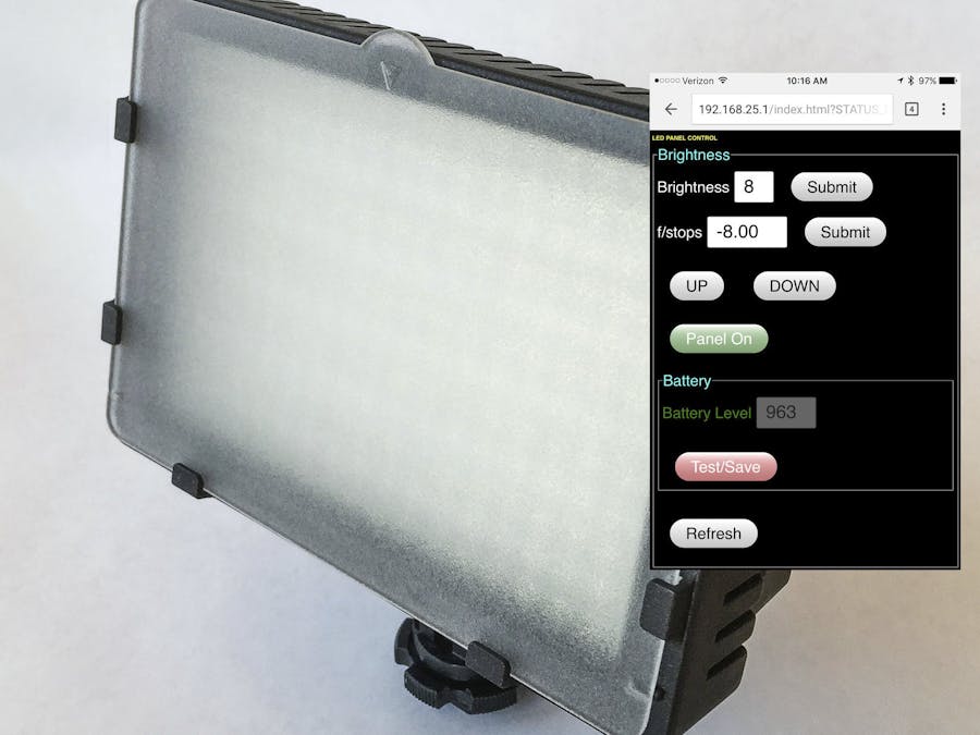
When you power on the device, the WiFi access point will be initialized. When the panel lights up, this indicates that the WiFi access point is also running. If you look at the list of available networks on your device, you'll see the name you entered in the "ESP_Identifier" table in WiFi.cpp (see Implementation Notes, Firmware, below). Select this network. The last 2 digits of the SSID are the subnet address. This tells you what address to use in the browser. The IP address is of the form: 192.168.X.1, where "X" is the subnet. For example, if the SSID is "RR_LED25", then you would go to "192.168.25.1" in your browser. You might want to bookmark this address and give it a name that makes sense to you so you won't need to work this out next time.
Once connected, the browser will bring up the user interface.
The interface has 2 sections, each surrounded by a thin white line.
The first is the Brightness section. There are two ways to directly enter the output value: Brightness and f/stop. For each, it is necessary to press the "Submit" button next to the input field to send the value to the device. These two numbers are always linked, and represent two different approaches to setting the light output: brightness works like a volume knob, and f/stop works like your camera's aperture. Increasing the brightness value by 1 will increase light output by 1/2 f/stop. You can enter a brightness level from 0 (off) to 24 (max) in whole numbers. For example, increasing brightness from 10 to 12 will output by 1 full stop.
The f/stop value is always negative and indicates the number of f/stops of dimming. Thus, changing the f/stop value from -7.00 to -7.50 will decrease light output by 1/2 stop. You can enter an f/stop value from -12 (off) to (0) max in 0.5 increments (values other than this will be rounded off). Since these values are linked, entering a brightness of 10, for example, will change the f/stop value to -7.00 and vice-versa.
Beneath the input fields are the "UP" and "DOWN" buttons. These buttons works exactly the same as the physical buttons on the device.
Finally, there is the Panel on/off button at the bottom of this section. This enables or disables the panel - but it does not turn off the power. The label on the button indicates the current state: if the panel is enabled, the button will show "Panel On" in green; if it is disabled, it will show "Panel Off" in red.
Underneath the Brightness section is the Battery section. Pressing "Test/Save" is the same as pressing (and holding) the "TEST" button on the device. When you press the "Test/Save" button, it will turn green and the LED on the device will illuminate. Pressing it again will fill in the Battery Level value display above the button, disable the LED indicator on the device, turn the button color back to red, and change the Battery Level label color to match that of the current battery state. For example, if the battery level was orange (poor) then the label color will be orange as well. Note that the test function will be active as long as the "Test/Save" button is green; you must press it again to disable the test function (and the device LED).
Underneath the Battery section is a "Refresh" button. This will update the browser display to match the current device state. If you change values using the buttons on the LED panel, you must press "Refresh" to see these reflected in your browser.
Implementation- Remove both control boards, cutting the wires as close to the board as possible so they can be reused.
- Keep all of the screws as they will all be reused.
- The existing slot on the side for the potentiometer knob needs to be widened to accommodate the width of the switch. We used an X-Acto knife to do this.
- The 3D printed holder should be printed at 100% infill after the first 2.5mm (above the base). If your slicing software cannot change infill rates during the print, then print the entire part at 100% infill. (We used and recommend Simplify3D). As long as your device is not going to be exposed to excessive heat, PLA filament is fine (and what we used).
- The switch slot filler overhang is the only element that needs support. Since you need to disable support for the bottom proto board slot (so narrow it would be impossible to clean out the supports), if your slicing software does not have manual support placement then you should turn off support. In this case, you'll need to manually clean up the area under the switch slot filler block.
- The slot for the proto board that holds the TEST tactile switch will need to be manually cleaned up so the board slides freely in the slot. Some freedom of movement is important to make sure the switch lines up properly with the TEST plunger mounted to the enclosure.
- The holder has the top screw hole already placed, but you will need to measure and drill the bottom hole in the proto board. The hole is approximately 3mm in from the side and 5mm back from the bottom edge.
- Lining up the holes for the up and down buttons can be tricky. We temporarily mounted 2 tactile switches with shorter plungers that would just fit inside the case and marked the spot where they hit the side with a scribing tool. After drilling the holes (9/64" drill bit), replace the switches with the longer ones.
- Drill out the second LED hole from the TEST button with a 3/16" drill bit for the 5mm RBG LED. It will be a tight fit (on purpose).
- The panel that protects the LED contacts from shorting has some standoffs around the interior side of the holes. The other side is flat. We flipped this board around (standoffs against the enclosure) to provide more space for the PCB components, especially the heatsink.
- We made the PCB available for order on PCBs.io. PCBs.io is run by Digistump (makers of the Oak). They have a unique model that charges by the square inch and allows for quantities as small as 4. As of this writing, 4 boards were less than $13.
- We soldered the ESP8266 using a PCB stencil, solder paste, and a hot air rework station (see the BOM for the stencil vendor link). We chose this approach because we only have the one SMD part and were a bit concerned about putting the ESP8266 through a reflow oven. Search the web for instructions on how to solder SMD parts using a traditional soldering iron if you don't have a hot air rework station.
- All but a few resistors are mounted vertically to preserve space.
- Measure and solder all of the wires to the PCB before screwing it in. Applying flux to the pads will improve the solder flow and is recommended for all connections as a best practice. Use the left and right screw holes to mount the board to the enclosure.
- It is important to note that the voltage regulator is mounted with the plastic package down so the heatsink is facing up once the leads are bent over.
- The voltage regulator heatsink needs to be reduced to 6.5mm in height (measured on the side) to fit. We used an angle grinder with a diamond wheel (go slow - it's aluminum!) which will easily cut it down, but leaves a lot of material in the grooves. We removed this with a Dremel rotary tool using a thin diamond blade. You should also use a file to smooth out the areas you worked on. Rounding off the bottom heatsink edge that faces inwards also provides some clearance for the ground wire (GND pad) and the power wire (BATSW pad).
- The reset switch for flashing the ESP8266 is on the separate programming board. This board also has the FTDI header for the FTDI/USB programming cable.
- When connecting the programming leads between the main board and the programming board, be sure to reverse the sense of the TX/RX lines. E.g. TX from the cable goes to RX on the board. We arranged the connections so that this is a straight-through arrangement: the lines will be in the same order on both boards if you have connected them properly. The picture above is a bit obscured, but the sequence is yellow/white/blue/green (L to R) on the programming board, and the same sequence bottom to top on the main PCB.
ESP8266 settings in the IDE:
- Board: Generic ESP8266 Module
- Flash Mode: QIO
- Flash Frequency: 40MHz
- CPU Frequency: 160MHz
- Flash Size: 4M(1M SPIFFS)
- Debug port: Disabled
- Debug Level: None
- Reset Method: ck
- Upload Speed: 115200
- This code was developed using Arduino IDE 1.6.11.
- Important: The PWM fix is not yet in an ESP8266 core release. The current release is 2.3.0. If you are building this before the fix for #836 is in a release, then you need to use the live GitHub repo. If you don't, then you will see some occasional bright flashes at low light levels as well as noticeable flickering.
- Before uploading the firmware, upload and run the MacAddress.ino sketch, which will print the ESP8266 MAC address on the serial port. Then enter the last 2 bytes of the address in the IP address mapping table "ESP_Identifier" in WiFi.cpp.
- Edit "ESP_Identifier" for your desired SSIDs, passwords, and subnet addresses. Be sure to change the "ID_TABLE_SIZE" define also if needed.
- You need to upload the SPIFFS file system image using the flash upload tool. This can be done before or after loading the main firmware. If you forget, the battery LED will flash purple.
- To flash the ESP8266, before you can upload the firmware or the SPIFFS filesystem to the IDE, you must follow this switch sequence. (The "Flash" button is activated by the "TEST" button the back of the unit. The "Reset" button is on the programming board.)
Press & hold RESET; Press & hold TEST; release RESET; release TEST
Now initiate the upload.
- The ESP8266 is a bit finicky, so if the upload fails just repeat the above Reset/Flash sequence and try again.
Copyright 2016 Dan Lenardon and Rob Redford.
This work is licensed under the Creative Commons Attribution-NonCommercial-ShareAlike 4.0 International License.
To view a copy of this license, visit BY-NC-SA 4.0.


Comments